Additional information on the SIMOGEAR geared motor
11.2 Specific data motor
SINAMICS G115D distributed drive
Operating Instructions, 12/2020, FW V4.7 SP13, A5E48681219B-002
419
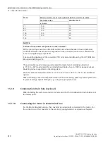
Limit values
The following limit values are valid for the insulation resistance at a rated voltage of U
N
< 2 kV
and a winding temperature of +25 °C.
500 V
Measuring circuit voltage
10
MΩ
Minimum insulation resistance for new, cleaned or repaired windings
0.5
MΩ
/ kV
Critical specific insulation resistance after a long operating time
Observe the following:
•
If you measure a winding temperature other than +25 °C, convert the measured value to
the reference tempe25 °C. The insulation resistance is halved for every 10 K
increase in temperature, and it is doubled for every 10 K decrease in temperature.
•
If the insulation resistance is close to or below the minimum value, the cause could be
humidity and dirt accumulation. Dry the windings.
•
During operation, the insulation resistance of the windings can fall to the critical
insulation resistance due to ambient and operational influences. To calculate the critical
insulation resistance value for a winding temperature of +25 °C, multiply the rated
voltage kV by the specific critical resistance value (0.5
MΩ
/ kV). Example: rated
voltage U
N
690 V: 690 V x 0.5
MΩ
/ kV = 0.345
MΩ.
11.2.13
Commissioning the motor
Note
Protect the motor against overload.
Do not exceed the maximum speed.
Note
With a brake with manual release:
No braking effect when the manual brake release lever is locked. The brake is then
permanently released.
Before commissioning the geared motor, ensure that the brake is not locked.
Unscrew the manual brake release lever and keep it separate from the geared motor.
Note
When starting / before switching on, use the appropriate circuit to ensure that the motor
brake is released.


