Electrical installation
4.10 Other connections
Converter cabinet units
Operating Instructions, 07/2016, A5E03347396A
137
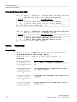
Cabinet unit settings
If the thermostatic switch for the braking resistor is connected, appropriate settings have to
be made so that the drive is brought to a standstill if a fault occurs.
Once the device has been successfully commissioned, you have to make the following
changes:
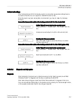
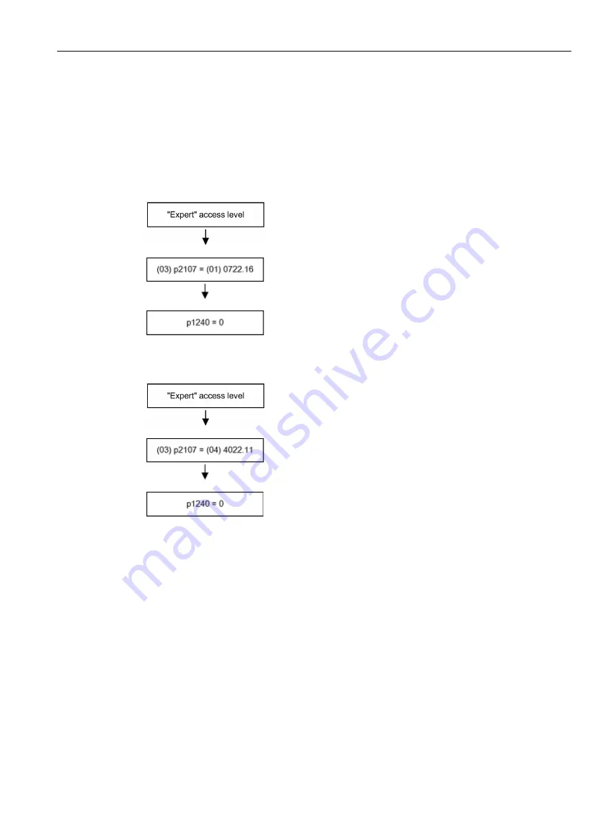
Connect the thermostatic switch of the braking resistor to DI 16 of the Control Unit
Set the "Expert" access level on the operator panel
<Key pushbutton> - <Access level> - Set "Expert" and con-
firm.
Interconnect external fault 2 to DI 16 of the Control Unit.
Disabling the Vdc-max controller
When the brake chopper is used, the Vdc-max controller
must be switched off.
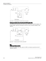
Connect the thermostatic switch of the braking resistor to DI 11 of the TM31 (option G60)
Set the "Expert" access level on the operator panel
<Key pushbutton> - <Access level> - Set "Expert" and con-
firm.
Switch external fault 2 to DI 11 on the TM31.
Disabling the Vdc-max controller
When the brake chopper is used, the Vdc-max controller
must be switched off.
4.10.11.2
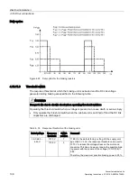
Diagnosis and duty cycles
Diagnosis
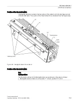
If the thermostat is opened due to a thermal overload on the braking resistor, fault F7861
("External Fault 2") is triggered and the drive is switched off with OFF2.
If the brake chopper triggers a fault, fault F7862 "External fault 3" is triggered in the drive.
You can acknowledge malfunctions in the braking unit by pressing the "Acknowledge" button
on the operator panel when the DC link voltage is present).
Summary of Contents for SINAMICS G150
Page 1: ......
Page 2: ......
Page 8: ...Foreword Converter cabinet units 8 Operating Instructions 07 2016 A5E03347396A ...
Page 18: ...Table of contents Converter cabinet units 18 Operating Instructions 07 2016 A5E03347396A ...
Page 679: ......
Page 680: ......

