Operation
6.8 Communication via PROFIBUS DP
Converter cabinet units
Operating Instructions, 07/2016, A5E03347396A
349
6.8.2
Control via PROFIBUS
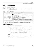
Diagnostics LED "COM (PROFIdrive)"
The PROFIBUS diagnostics LED is located on the front of the Control Unit. Its states are
described in the following table.
Table 6- 28 Description of the "COM" LED
Color
State
Description
-----
OFF
Cyclic communication is not (yet) running.
Note:
The PROFIdrive is ready for communication when the Control Unit is ready for opera-
tion (see LED RDY).
Green
Continuous light Cyclic communication is taking place.
Green
0.5 Hz flashing
light
Cyclic communication has still not been fully established.
Possible causes:
- The controller is not transmitting any setpoints.
- In isochronous mode, the controller did not send a Global Control or it sent a defec-
tive Global Control (GC).
Red
0.5 Hz flashing
light
PROFIBUS master is sending incorrect parameter assignment/configuration
Red
2 Hz flashing light Cyclic bus communication has been interrupted or could not be established.
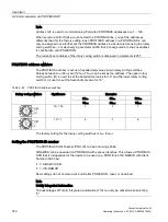
Setting the PROFIBUS address
There are two ways to set the PROFIBUS address:
1.
Via p0918
–
To set the bus address for a PROFIBUS node using STARTER, first set the rotary
code switches to 0
dec
(00
hex
) and 127
dec
(7F
hex
).
–
Then use parameter p0918 to set the address to a value between 1 and 126.
2.
Via the PROFIBUS address switches on the Control Unit
–
The address is set manually to values between 1 and 126 using the rotary coding
switches. In this case, p0918 is only used to read the address.
Note
The rotary coding switches used to set the PROFIBUS address are located beneath the
cover.
Summary of Contents for SINAMICS G150
Page 1: ......
Page 2: ......
Page 8: ...Foreword Converter cabinet units 8 Operating Instructions 07 2016 A5E03347396A ...
Page 18: ...Table of contents Converter cabinet units 18 Operating Instructions 07 2016 A5E03347396A ...
Page 679: ......
Page 680: ......


