Functions, monitoring, and protective functions
9.2 Drive functions
Converter cabinet units
Operating Instructions, 07/2016, A5E03347396A
519
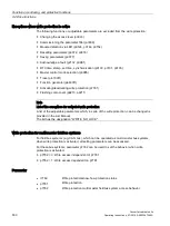
A pulse inhibit must be set prior to attempting reversal.
Direction reversal can be set differently for each drive data set.
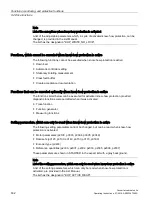
Note
Drive data set changeover with differently set direction reversal
When changing over the drive data set to differently set reversing and with pulse approval,
fault F7434 is issued.
Reversing can be observed by checking parameters r0069 (phase currents) and r0089
(phase voltage). The absolute position reference is lost on reversal.
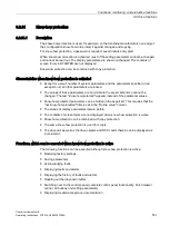
The output direction of rotation of the converter can be additionally reversed using p1820.
This means that the rotating field can be changed without having to interchange the power
connections. If an encoder is being used, the direction of rotation must, when required, be
adapted using p0410.
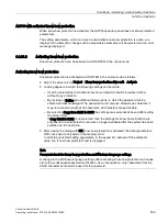
NOTICE
Material damage when the drive undesirably accelerates with an external speed actual
value
When using an external speed actual value for the speed controller via p1440, positive
feedback can occur in the speed control loop. As a consequence, the drive accelerates up
to its speed limit and can be damaged.
•
When using external speed actual values for the speed controller, additionally change
its polarity when reversing the direction of rotation (p1821 = 1).
WARNING
Danger to life as a result of an excessively high torque due to an inappropriate phase
sequence of the motor after direction reversal
If a drive is synchronized to the line supply, when the direction is reversed, high torques
can be generated when connecting to the line supply if the phase sequence of the line
voltage does not match the phase sequence of the rotating motor. This high torque can
destroy the coupling between the motor and load and therefore result in death or severe
injury.
•
As a consequence, for this constellation, check the phase sequence of the VSM wiring
and correct if necessary.
Function diagram
FP 4704, 4715
Encoder evaluation
FP 6730, 6731
Interface to the Motor Module
Summary of Contents for SINAMICS G150
Page 1: ......
Page 2: ......
Page 8: ...Foreword Converter cabinet units 8 Operating Instructions 07 2016 A5E03347396A ...
Page 18: ...Table of contents Converter cabinet units 18 Operating Instructions 07 2016 A5E03347396A ...
Page 679: ......
Page 680: ......


