Functions, monitoring, and protective functions
9.3 Extended functions
Converter cabinet units
Operating Instructions, 07/2016, A5E03347396A
555
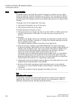
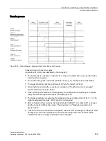
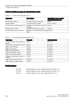
Transfer process
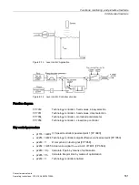
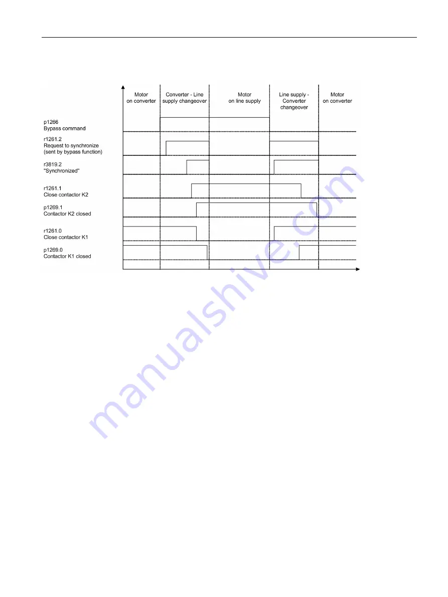
Figure 9-16 Signal diagram, bypass with synchronization with overlap
Transfer of motor to the line supply
(contactors K1 and K2 are activated by the converter):
●
The initial state is as follows: Contactor K1 is closed, contactor K2 is open and the motor
is fed from the converter.
●
The control bit "bypass command" (p1266) is set (e.g. by the higher-level automation).
●
The bypass function sets the control word bit "synchronizing" (r1261.2).
●
Since the bit is set while the converter is running, the "Transfer motor to line supply"
synchronization process is started.
●
Once motor synchronization to line frequency, line voltage and line phasing is complete,
the synchronization algorithm reports this state (r3819.2).
●
The bypass mechanism evaluates this signal and closes contactor K2 (r1261.1 = 1). The
signal is evaluated internally - BICO wiring is not required.
●
After contactor K2 has fed back the "closed" state (r1269[1] = 1), contactor K1 is opened
and the converter inhibits the pulses. The converter is in "Ready for operation and
bypass" state.
●
If the On command is cancelled in this phase, the converter will change to "Ready to start
and bypass" state. If the appropriate contactors are being used, the converter will be
isolated from the line supply and the DC link discharged.
Summary of Contents for SINAMICS G150
Page 1: ......
Page 2: ......
Page 8: ...Foreword Converter cabinet units 8 Operating Instructions 07 2016 A5E03347396A ...
Page 18: ...Table of contents Converter cabinet units 18 Operating Instructions 07 2016 A5E03347396A ...
Page 679: ......
Page 680: ......

