Functions, monitoring, and protective functions
9.3 Extended functions
Converter cabinet units
560
Operating Instructions, 07/2016, A5E03347396A
Parameterization
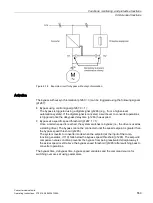
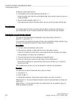
Once the bypass without synchronization (p1260 = 3) function has been activated, the
following parameters must be set.
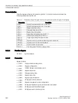
Table 9- 9
Parameter settings for bypass function with synchronizer without degree of overlapping
Parameters
Description
r1261.0
Signal "Command switch motor - power unit"
r1261.1
Signal "Command switch motor - line supply"
p1262 =
Bypass dead time setting
p1263 =
Debypass delay time setting
p1264 =
Bypass delay time setting
p1265 =
Speed threshold setting when p1267.1 = 1
p1266 =
Control signal setting when p1267.0 = 1
p1267.0 =
p1267.1 =
Trigger signal setting for bypass function
p1269[0] =
Signal source to provide the feedback signal of contactor K1
p1269[1] =
Signal source for contactor K2 feedback
p3800 = 0
Synchronization is deactivated.
P1200 = 1
The "flying restart" function is always active.
9.3.2.4
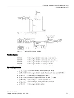
Function diagram
FP 7020
Synchronization
9.3.2.5
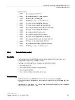
Parameters
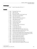
Bypass function
•
p1200
Flying restart operating mode
•
p1260
Bypass configuration
•
r1261
CO/BO: Bypass control/status word
•
p1262
Bypass dead time
•
p1263
Debypass delay time
•
p1264
Bypass delay time
•
p1265
Bypass speed threshold
•
p1266
BI: Bypass control command
•
p1267
Bypass changeover source configuration
•
p1268
BI: Bypass feedback signal synchronization completed
•
p1269
BI: Bypass switch feedback signal
•
p1274
BI: Bypass switch monitoring time
Summary of Contents for SINAMICS G150
Page 1: ......
Page 2: ......
Page 8: ...Foreword Converter cabinet units 8 Operating Instructions 07 2016 A5E03347396A ...
Page 18: ...Table of contents Converter cabinet units 18 Operating Instructions 07 2016 A5E03347396A ...
Page 679: ......
Page 680: ......

