Electrical installation
4.10 Other connections
Converter cabinet units
136
Operating Instructions, 07/2016, A5E03347396A
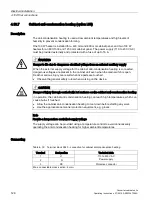
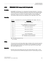
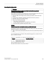
Connecting the thermostatic switch
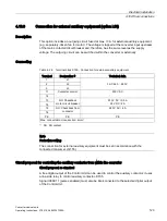
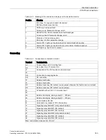
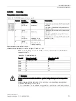
Table 4- 37 Installing the thermostatic switch for the external braking resistor in the monitoring circuit
of the cabinet unit by connecting to the Control Unit (without option G60)
Terminal
Description of function
T1
Thermostatic switch connection: connection with terminal X132:9 (DO12)
T2
Thermostatic switch connection: connection with terminal X122:5 (DI16)
Max. connectable cross-section (due to CU320-2): 1.5 mm²
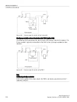
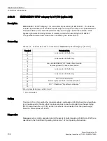
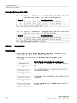
Table 4- 38 Installing the thermostatic switch for the external braking resistor in the monitoring circuit
of the cabinet unit by connecting to the TM31 (with option G60)
Terminal
Description of function
T1
Thermostatic switch connection: connection with terminal X541:1 (P24 V)
T2
Thermostatic switch connection: connection with terminal X541:5 (DI11)
Max. connectable cross-section (due to TM31): 1.5 mm²
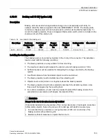
4.10.11.1
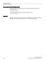
Commissioning
Commissioning
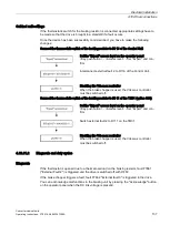
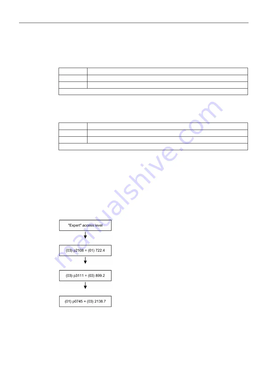
When commissioning via STARTER, parameters are assigned to "external fault 3" and
acknowledged automatically when option L62 is selected.
When commissioning via AOP30, the parameter entries required have to be set
subsequently.
Set the "Expert" access level on the operator panel
<Key pushbutton> - <Access level> - Set "Expert" and con-
firm.
Connect digital input 4 (DI4) on the Control Unit to the first
input of "External fault 3."
Connect the "Operation" signal to the second input of "Exter-
nal fault 3."
Connect "Acknowledge fault" to digital output 15 (DO15) on
the Control Unit.
Summary of Contents for SINAMICS G150
Page 1: ......
Page 2: ......
Page 8: ...Foreword Converter cabinet units 8 Operating Instructions 07 2016 A5E03347396A ...
Page 18: ...Table of contents Converter cabinet units 18 Operating Instructions 07 2016 A5E03347396A ...
Page 679: ......
Page 680: ......

