Electrical installation
4.10 Other connections
Converter cabinet units
194
Operating Instructions, 07/2016, A5E03347396A
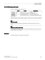
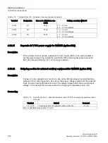
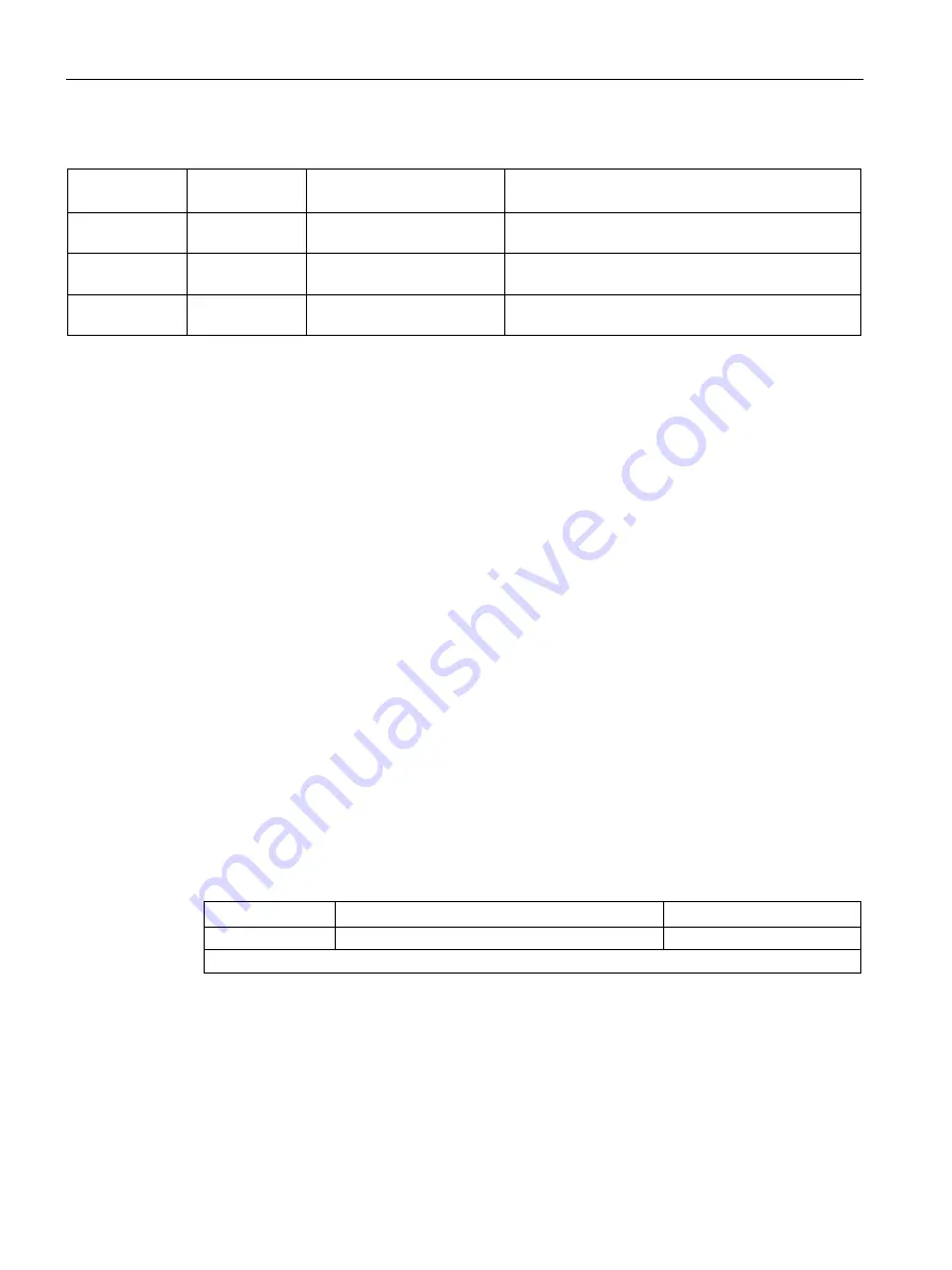
Table 4- 73 Terminal block -X2 – Adaptation of analog inputs and outputs
Terminal
Designation
Item code of interface con-
verter
Settings on rotary switch S1
50/51
AI
T401
2: 0 ... 20 mA
4: 4 ... 20 mA (default)
60/61
AO
T402
1: 0 ... 20 mA
2: 4 ... 20 mA (default)
62/63
AO
T403
1: 0 ... 20 mA
2: 4 ... 20 mA (default)
4.10.31
Separate 24 V DC power supply for NAMUR (option B02)
Description
If the customer cannot provide a separate 24 V DC supply (PELV), this option enables a
second power supply to be installed to provide the PELV (terminal assignment as option
B00, 24 V infeed at terminal -X1:1,2,3 no longer needed).
4.10.32
Outgoing section for external auxiliary equipment for NAMUR (option B03)
Description
If power is to be supplied to a motor fan on site, option B03 provides an uncontrolled fuse-
protected (10 A) outgoing section. As soon as the supply voltage is present at the converter
input, it is also present at these terminals. The voltage corresponds to the converter input
voltage. You must take this into account when configuring the separately driven fan.
Connecting
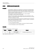
Table 4- 74 Terminal block -X1 – uncontrolled power outlet (10 A) for supplying a separately driven
motor fan
Terminal
Default
Comment
1, 2, 3, PE
Outgoing section for separately driven motor fan
U = U
line
Max. connectable cross-section: 2.5 mm²
Summary of Contents for SINAMICS G150
Page 1: ......
Page 2: ......
Page 8: ...Foreword Converter cabinet units 8 Operating Instructions 07 2016 A5E03347396A ...
Page 18: ...Table of contents Converter cabinet units 18 Operating Instructions 07 2016 A5E03347396A ...
Page 679: ......
Page 680: ......

