Electrical installation
4.6 Electrical connection
Converter cabinet units
80
Operating Instructions, 07/2016, A5E03347396A
4.6.4
Connecting the power supply and the signal cables
Connecting the power supply and the signal cables
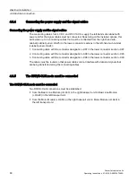
The connecting cables for 24 V DC and 230 V AC to supply the left-hand sub-cabinet with
power and for the signal cables must be connected. Depending on the installed options, this
will involve up to 3 connecting cables that must be connected from the right-hand sub-
cabinet (cabinet panel +H.A25) to the lower connector sections in the left-hand sub-cabinet
(cabinet panel +H.A24):
1.
Connecting cable with the connector designation –X97 in the lower connector section –X97.
2.
Connecting cable with the connector designation –X98 in the lower connector section –X98.
3.
Connecting cable with the connector designation –X99 in the lower connector section –X99.
The cables must be routed so that power cables cannot interfere with data and signals that
are being transferred along the connecting cables.
4.6.5
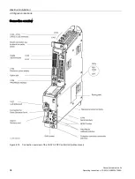
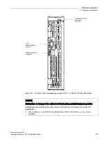
The DRIVE-CLiQ node must be connected
The DRIVE-CLiQ node must be connected
Two DRIVE-CLiQ connections must be established:
●
from the Basic Line Module (+H.A30) in the right transport unit to Basic Line Module
(+H.A29) in the left transport unit
●
from the Motor Module (+H.A50) in the right transport unit to Motor Module (+H.A49) in
the left transport unit
Summary of Contents for SINAMICS G150
Page 1: ......
Page 2: ......
Page 8: ...Foreword Converter cabinet units 8 Operating Instructions 07 2016 A5E03347396A ...
Page 18: ...Table of contents Converter cabinet units 18 Operating Instructions 07 2016 A5E03347396A ...
Page 679: ......
Page 680: ......

