PROFIBUS address switches
③
The PROFIBUS address switch is located under the cover.
ི
Figure 7-3
PROFIBUS address switch cover
7.1.2
Connecting PROFIBUS cables
The figure below shows suitable PROFIBUS connectors with/without a programming
device/PC connector.
352),%86FRQQHFWRUV
ZLWKRXW3*3&FRQQHFWLRQ
(6%$;$
352),%86FRQQHFWRUV
ZLWKSURJUDPPLQJGHYLFH3&
FRQQHFWLRQ
(6%%;$
Figure 7-4
PROFIBUS connectors
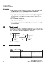
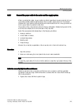
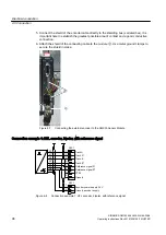
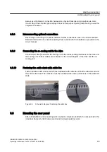
1. Connect the cables to the PROFIBUS connector. The bus terminating resistors are located
in this connector.
2. Connect the cable shield over a wide area on both sides.
Switching the bus terminating resistor on and off
1. Activate the bus terminating resistor at the two ends of the bus line.
2. Deactivate the bus terminating resistor at all other connectors.
Start-up
7.1 Description and configuration of the PROFIBUS interface
SINAMICS GM150 6SL3835-2LN44-2AA0
104
Operating Instructions Rev.201910281250 MUSTER
Summary of Contents for Sinamics GM150 6SL3835-2LN44-2AA0
Page 2: ...28 10 2019 12 50 V32 00 ...
Page 232: ...Index SINAMICS GM150 6SL3835 2LN44 2AA0 232 Operating Instructions Rev 201910281250 MUSTER ...
Page 233: ......
Page 236: ......
Page 238: ......


