Installing/mounting
4.5 Additional components
Power Module PM240-2
Hardware Installation Manual, 01/2017, A5E33294624B AE
39
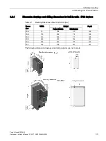
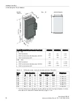
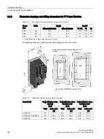
Table 4- 5
Drilling dimensions, cooling clearances and fixing
Frame
size
Control cabinet cutout [mm]
Cooling air clearances
[mm]
1)
Fixing/torque
a
b
c
d
e
Top
Bottom Front
FSA
103 106
27
198
88
80
100
100
8 x M5 / 3.5 Nm
FSB
148 134 34.5 304 116
80
100
100
8 x M5 / 3.5 Nm
FSC
123 174 30.5 365 156
80
100
100
10 x M5 / 3.5 Nm
1)
The Power Modules are designed for mounting without any lateral cooling air clearance. For toler-
ance reasons, we recommend a lateral clearance of 1 mm.
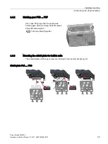
4.4.5
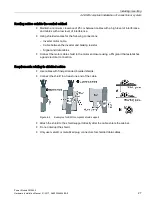
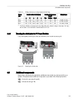
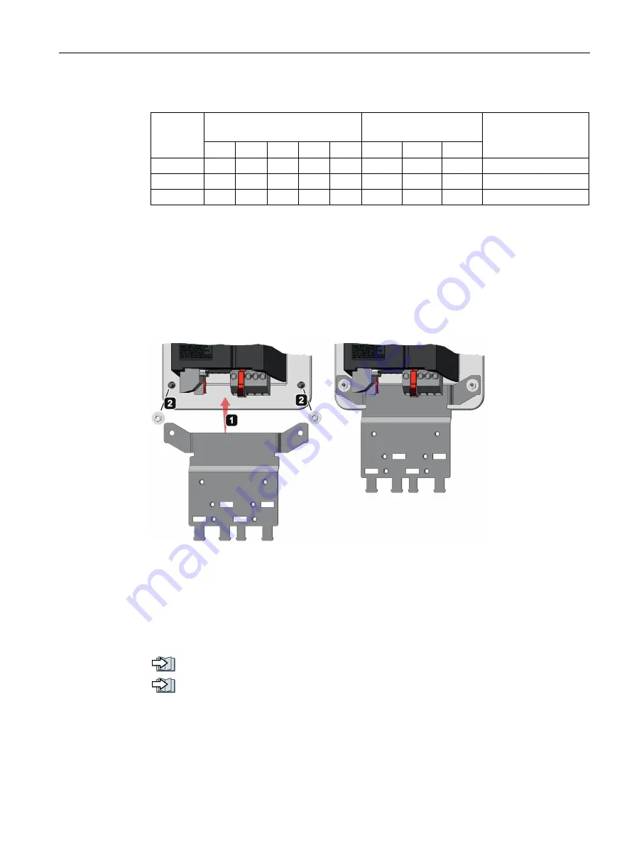
Mounting the shield plate for PT Power Modules
The shield plates and fixings screws are included in the inverter accessory kit.
Figure 4-5
Mounting the shield plate
4.5
Additional components
Depending on the particular application, additional components may be required for your
system. Information about additional components is provided in the following Sections:
Connection overview (Page 49)
Accessories (Page 105).
Summary of Contents for SINAMICS PM240-2
Page 1: ......
Page 2: ......
Page 8: ...Table of contents Power Module PM240 2 8 Hardware Installation Manual 01 2017 A5E33294624B AE ...
Page 104: ...Spare parts Power Module PM240 2 104 Hardware Installation Manual 01 2017 A5E33294624B AE ...
Page 143: ......
Page 144: ......

