Accessories
9.5 Braking resistor
Power Module PM240-2
Hardware Installation Manual, 01/2017, A5E33294624B AE
115
9.5
Braking resistor
The braking resistor enables loads with a large moment of inertia to be braked quickly.
During braking of the motor and the load, excess energy is fed back to the converter. This
causes the voltage to rise in the DC link. The converter transfers the excess energy to the
externally mounted braking resistor.
WARNING
Danger to life due to fire spreading because of an unsuitable or improperly installed braking
resistor
Using an unsuitable or improperly installed braking resistor can cause fires and smoke to
develop. Fire and smoke development can cause severe personal injury or material
damage.
•
Only use braking resistors that are approved for the inverter.
•
Install the braking resistor in accordance with regulations.
•
Monitor the temperature of the braking resistor.
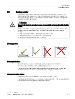
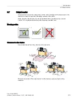
Mounting position
Mounting instructions
Mount the resistor on a heat resistant surface with a high thermal conductivity.
Do not cover the ventilation openings of the braking resistor.
You can mount the braking resistor either outside or inside the switchgear room. When
mounted outside, the cooling air requirement for the switchgear room is lower.
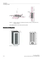
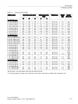
Clearances to other devices
The following data are applicable for devices, frame sizes FSA … FSC.
The clearances for braking resistors for devices, frame sizes FSD … FSF are specified in the
documentation, which is supplied with the braking resistor.
Summary of Contents for SINAMICS PM240-2
Page 1: ......
Page 2: ......
Page 8: ...Table of contents Power Module PM240 2 8 Hardware Installation Manual 01 2017 A5E33294624B AE ...
Page 104: ...Spare parts Power Module PM240 2 104 Hardware Installation Manual 01 2017 A5E33294624B AE ...
Page 143: ......
Page 144: ......

