Commissioning
5.5 First commissioning
Drive converter cabinet units
164
Operating Instructions, 07/07, A5E00288214A
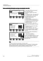
Encoders for SMC30:
3001:
1024 HTL A/B R at X521/X531
3002:
1024 TTL A/B R at X521/X531
3003:
2048 HTL A/B R at X521/X531
3005:
1024 HTL A/B at X521/X531
3006:
1024 TTL A/B at X521/X531
3007:
2048 HTL A/B at X521/X531
3008:
2048 TTL A/B at X521/X531
3009
1024 HTL A/B unipolar at X521/X531
3011:
2048 HTL A/B unipolar at X521/X531
3020:
2048 TTL A/B R with sense to X520
3081:
SSI, Singleturn, 24 V
3082:
SSI, Multiturn 4096, 24 V
3090:
4096, HTL, A/B, SSI, Singleturn
Note
The chapter ("Electrical installation") contains connection examples for standard encoders.
Note
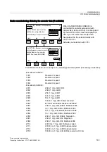
If the connected encoder does not match any of the encoders predefined in p0400, follow the
simple procedure below for entering the encoder data:
•
Via p0400, select an encoder type whose data is similar to that of the connected encoder.
•
Select "User-defined" (p0400 = 9999). Previously set values are stored here.
•
Adjust the bit fields of p0404, p0405, and p0408 to the data for the connected encoder.
Table 5-3
Meaning of the bit settings for p0404
Bit
Meaning
Value 0
Value 1
20
Voltage 5 V
No
Yes
21
Voltage 24 V
No
Yes
Table 5-4
Meaning of the bit settings for p0405
Bit
Meaning
Value 0
Value 1
0
Signal
Unipolar
Bipolar
1
Level
HTL
TTL
2
Track monitoring
None
A/B <> -A/B
3
Zero pulse
24 V unipolar
Same as A/B track


