Operation
6.3 Basic information about the drive system
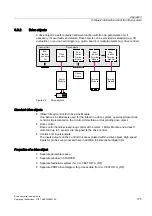
Drive converter cabinet units
Operating Instructions, 07/07, A5E00288214A
185
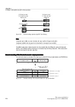
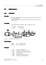
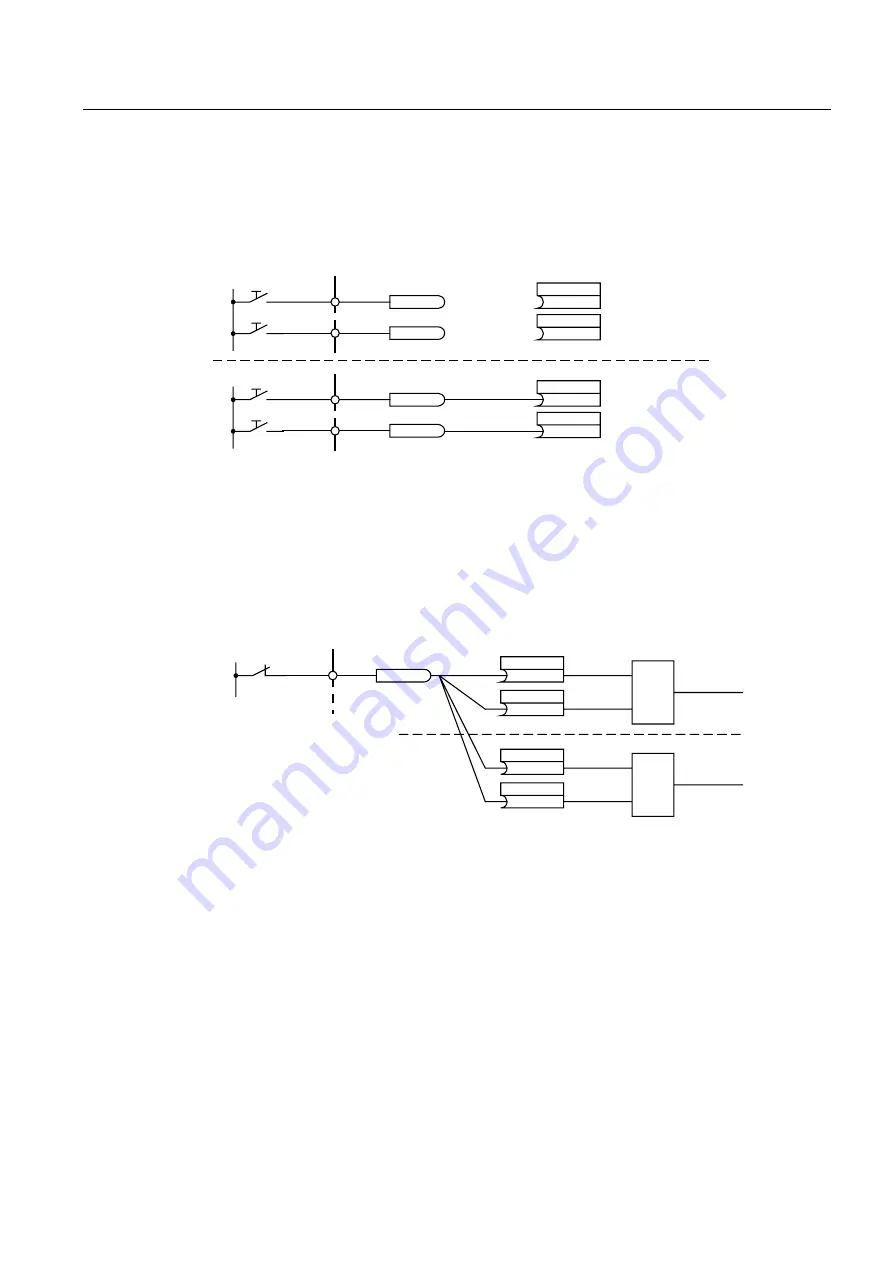
Example 1: interconnecting digital signals
Suppose you want to operate a drive via terminals DI 0 and DI 1 on the Control Unit using
jog 1 and jog 2.
%2%LQHFWRURXWSXW
6LJQDOVRXUFH
%,%LQHFWRULQSXW
6LJQDOVLQN
-RJ
-RJ
-RJ
-RJ
,QWHUQDO
,QWHUQDO
U
U
',
;
',
;
S&
S&
9
U
U
',
;
',
;
S&
S&
9
Figure 6-7
Interconnection of digital signals (example)
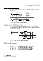
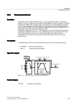
Example 2: connection of OC/OFF3 to several drives
The OFF3 signal is to be connected to two drives via terminal DI 2 on the Control Unit.
Each drive has a binector input 1. OFF3 and 2. OFF3. The two signals are processed via an
AND gate to STW1.2 (OFF3).
%2%LQHFWRURXWSXW
6LJQDOVRXUFH
%,%LQHFWRULQSXW
6LJQDOVLQN
'ULYH
'ULYH
2))
2))
2))
2))
2))
2))
',
U
;
9
S&
S&
S&
S&
Figure 6-8
Connection of OFF3 to several drives (example)
BICO interconnections to other drives
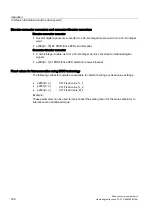
The following parameters are available for BICO interconnections to other drives:
•
r9490
Number of BICO interconnections to other drives
•
r9491[0...15]
BI/CI of BICO interconnections to other drives
•
r9492[0...15]
BO/CO of BICO interconnections to other drives
•
p9493[0...15]
Reset BICO interconnections to other drives

