Operation
6.6 PROFIBUS
Drive converter cabinet units
Operating Instructions, 07/07, A5E00288214A
209
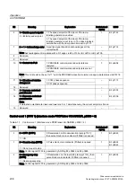
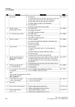
Bit
Meaning
Explanation
Betriebsbedi
ngung
BICO
1: Enable inverter, pulse enable, ramp-up with active
setpoint
3
0 = Disable operation
1 = Enable operation
0: Pulse inhibit. The motor coasts down. The "Ready
To Run" status remains set.
1
BI: p0852
0: The ramp generator output is set to setpoint "0".
4
0 = Set ramp generator to
zero
1 = Enable ramp-function
generator
1
BI: p1140
0: The current setpoint is frozen at the ramp
generator output.
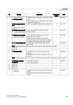
5
0 = Freeze ramp generator
1 = Restart ramp generator
1
BI: p1141
1: The speed setpoint at the input of the ramp-
function generator is enabled.
6
1 = Enable speed setpoint
0 = Inhibit speed setpoint
0: The speed setpoint at the input of the ramp-
function generator is set to zero. The drive brakes in
accordance with the ramp-down time set in p1121.
1
BI: p1142
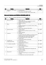
0 -> 1 = Acknowledge error A positive signal transition acknowledges all the
current faults
–
BI: p2103
7
Note: Acknowledgement is realized with a 0/1 edge via BI: p2103 or BI: p2104 or BI: p2105.
8
Reserved
–
–
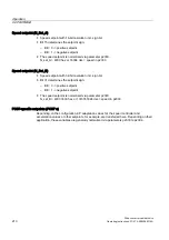
9
Reserved
–
–
1: PROFIBUS control words and setpoints are
analyzed.
1 = Control via PLC
0: PROFIBUS control words and setpoints are not
analyzed.
1
BI: p0854
10
Note: This bit should not be set to "1" until the PROFIBUS slave has returned an appropriate status via STW1.9
= "1".
1: CCW phase sequence
11
1 = Direction of rotation
changeover
0: CW phase sequence
–
BI: p1113
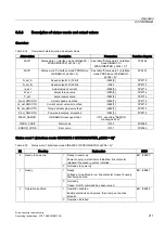
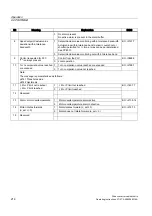
12
Reserved
–
–
13
Reserved
–
–
14
Reserved
–
–
1: Parameter data set changeover (DDS) data set 2
is active
15
1 = Data set 2
0 = Data set 1
0: Parameter data set changeover (DDS) data set 1
is active
–
BI: p0820

