Functions, monitoring, and protective functions
9.2 Active Infeed functions
Drive converter cabinet units
Operating Instructions, 07/07, A5E00288214A
307
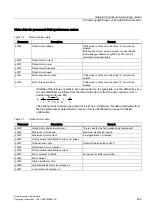
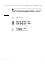
Example 2: Faults during operation when loading the infeed, operating on a "normal" supply.
Power failure (F6200, A6205), DC link overvoltage (F30002)
Following procedure:
1.
Exclude other sources of fault: e.g. actual power failure, wiring fault, correct supply data
setting (p0210, p0211)
2.
If 1. is not successful, then in addition (for FW ≤ 2.4 only):
Gradual increase in value of infeed inductance between supply and filter p0225 (initial
value: 0.3/0.5/0.7 x p0223),
Limit p3421 to 2 x p0233
→ Start each supply ID (p3410 = 5)
3.
If 2. is not successful, then in addition:
p3463 Infeed, line angle change, phase failure detection = 15° ... 30°
p3458[1] Infeed PLL smoothing time = 8 ms .. 25 ms
(both parameters only visible at service access level)
→ Run load test
4.
If 3. is not successful, then in addition:
Change controller gain p3560 = 10% .. 300%
and, if necessary, integral action time p3562 = 50% (Vdc controller)
→ Run load test
5.
If 4. is not successful, then in addition:
Change voltage setpoint p3510, increase or decrease depending on fault pattern and
application
→ Run load test
6.
If 5. is not successful, then in addition:
p3530 Set motorized infeed current limit to active infeed rated current (r0207).
Set p3531 Regenerating infeed current limit to the negative active infeed rated current
value (r0207)
→ Run load test
Note
The service parameters can only be accessed by authorized Siemens personnel.
If a particular setting is not possible or special application-specific supplementary
conditions are present, individual steps can also be omitted.

