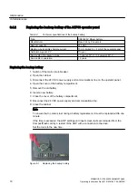
I/O connection
● Create a low-impedance ground connection for additional cabinets, system components,
and distributed devices with the largest possible cross-section (at least 16 mm²).
● Ground unused lines at one end in the cabinet.
● Choose the greatest possible clearance between the power and signal cables (at least 20
cm). The greater the distance over which the cables are routed in parallel, the greater the
clearance must be. You must install additional shields if sufficient clearance cannot be
maintained.
● Avoid unnecessarily long cable loops.
● Surge suppressors – e.g. RC elements or varistors – must be connected to the solenoids of
contactors and relays in the device.
● In order to reduce noise/interference entering or exiting via the cable, filter auxiliary voltages
in the control cabinet.
6.4
Using the equipotential bonding strip and shield bus
Each cabinet is equipped with an equipotential bonding or grounding bar to make it simpler to
connect equipotential bonding conductors.
Connect all internal and external components to this equipotential bonding busbar. is Attach the
shields of incoming and outgoing cables directly to the shield bus. It is important here to
establish the greatest possible area of contact and a good conductive connection.
bP
&DELQHW
ILUPO\FRQQHFWHGWRWKH
YHUWLFDOFDELQHW
7RRWKHUV\VWHP
FRPSRQHQWV
(TXLSRWHQWLDOEXVEDU
6KLHOGLQJEXV
6HUUDWHGEXVEDU
&RQWUROV\VWHP
3RZHU
FRPSRQHQWV
7HUPLQDOEORFN
Figure 6-3
Equipotential bonding strip
Electrical connection
6.4 Using the equipotential bonding strip and shield bus
SINAMICS SL150 6SL38655UM427AA02
56
Operating Instructions Rev.201910281507 EXAMPLE

