Parameter list
8.2 Parameter list
SINAMICS V20 Converter
222
Operating Instructions, 10/2019, A5E34559884-012
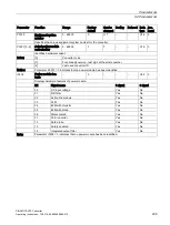
Parameter
Function
Range
Factory
default
Can be
changed
Scaling
Data
set
Data
type
Acc.
Level
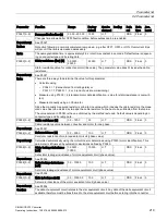
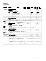
P0610[0...2] Motor I
2
t temperature reac-
tion
0 - 6
6
T
-
DDS
U16
3
Defines reaction when motor temperature reaches warning threshold.
0
Warning only. Does not recall the motor temperature (stored at power down)
on power up
1
Warning with Imax control (motor current reduced) and trip (F11). Does not
recall the motor temperature (stored at power down) on power up
2
Warning and trip (F11). Does not recall the motor temperature (stored at
power down) on power up
4
Warning only. Recalls the motor temperature (stored at power down) on
power up
5
Warning with Imax control (motor current reduced) and trip (F11). Recalls
the motor temperature (stored at power down) on power up
6
Warning and trip (F11). Recalls the motor temperature (stored at power
down) on power up
Dependency: Trip level = P0604 (motor temperature threshold) * 110 %
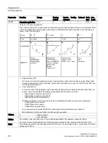
Note:
•
P0610 = 0 (No reaction, warning only)
When temperature reaches warning level defined in P0604, the converter displays warning A511, no reac-
tion is done.
•
P0610 = 1 (Warning, Imax reduction and Trip)
When temperature reaches warning level defined in P0604, the converter displays warning A511, reduce
frequency and trips F11, when temperature exceeds the trip level.
•
P0610 = 2 (Warning and trip F11)
When temperature reaches warning level defined in P0604, the converter displays warning A511 and trips
F11, when temperature exceeds the trip level.
The purpose of motor I
2
t is to calculate the motor temperature and disable the converter if the motor is in
danger of overheating.
I
2
t operation:
The measured motor current is displayed in r0027. The motor temperature in °C is displayed in r0035.
This temperature is derived from a calculated value using motor thermal model.
The reaction to the warning can be changed from this default using P0610.
r0035 is particularly useful to monitor if the calculated motor temperature is rising excessively.
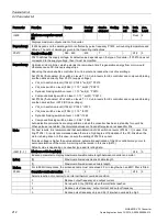
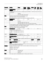
P0622[0...2] Magnetizing time for temp
id after start up [ms]
0.000 - 20000
0.000
U, T
-
DDS
Float 3
Specifies the magnetization time for stator resistance identification.
r0623[0...2]
CO: Display for the identi-
fied stator resistance [Ω]
-
-
-
-
DDS
Float 4
Display of the actual identified stator resistance after temperature identification.
P0625[0...2] Surrounding motor temper-
ature [°C]
-40.0 - 80.0
20.0
C, U, T -
DDS
Float 3
Surrounding temperature of motor at time of motor data identification. It is only allowed to change the
value when the motor is cold. A motor identification has to be made after changing the value.
Dependency: This parameter is influenced by automatic calculations defined by P0340.
Summary of Contents for SINAMICS V20 Inverter
Page 1: ...SINAMICS V20 Converter ...
Page 2: ......
Page 8: ...Preface SINAMICS V20 Converter 6 Operating Instructions 10 2019 A5E34559884 012 ...
Page 426: ......


