Start-Up
SINUMERIK 801
2-17
Start-Up
R S 2 3 2 a d a p ter
9 P IN S U B -D (so c k e t)
P C
2 5 P IN S U B -D (p lu g )
R x D 2
T x D
3
D T R 4
D S R 6
0 V 5
R x D
3
T x D
2
D T R
2 0
D S R
6
0 V
7
R T S 7
R T S
4
C T S 8
C T S
5
0 .1
m m
2
X2
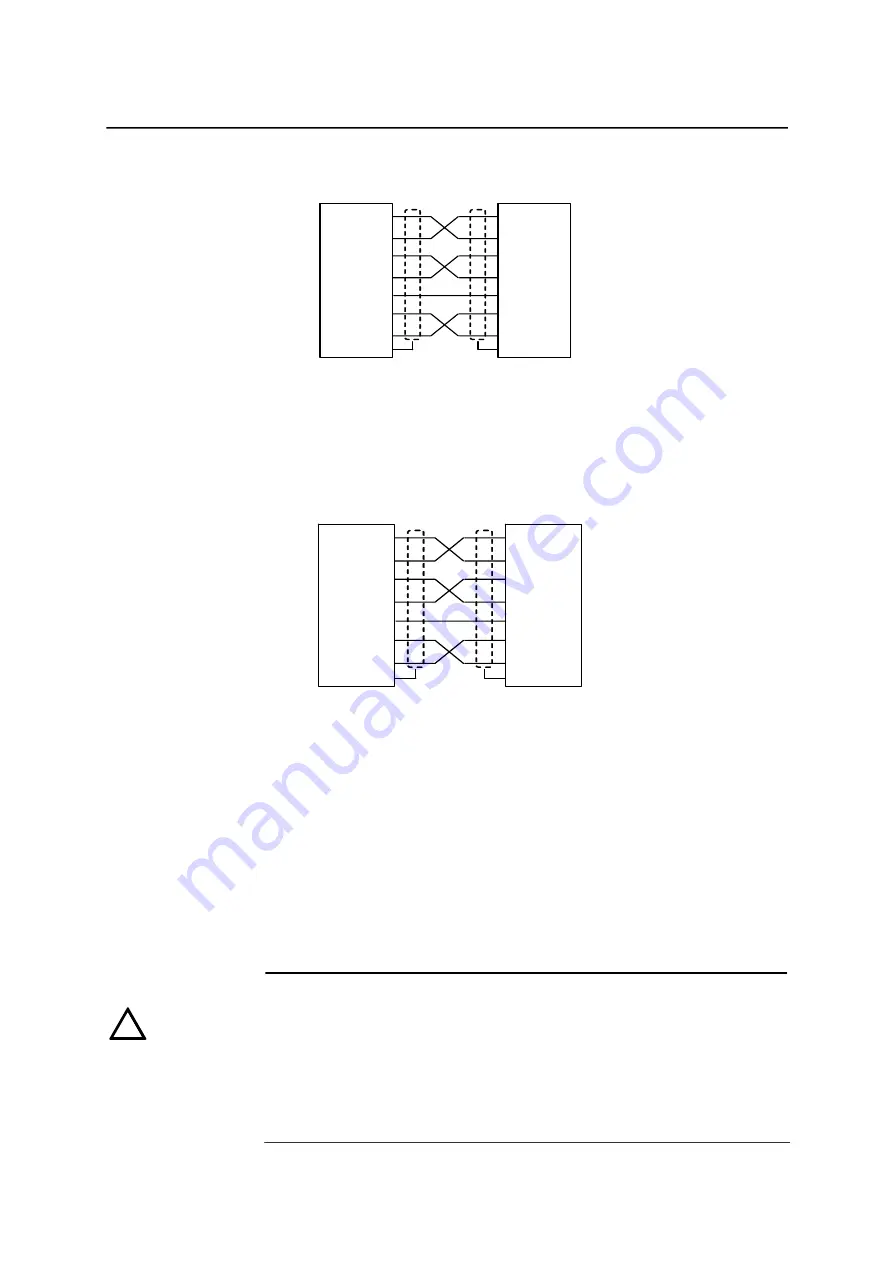
Fig. 2-18 Connecting diagram 2 (with 25PIN SUB-D connector of PC Serial
Port)
(2) The connecting diagram between the RS232 adapter and SINUMERIK
801
R S 2 3 2 a d a p te r
9 P IN S U B -D (so c k e t)
S IN U M E R IK 8 0 1
9 P IN S U B -D (s o c ke t)
R x D 2
T x D 3
D T R 4
D S R 6
0 V
5
R x D
2
T x D
3
D T R
4
D S R
6
0 V
5
0 .1 m m
2
R T S 7
R T S
7
C T S 8
C T S
8
X1
Fig.2-19 Connecting diagram 3 (with SINUMERIK 801)
Notes:
(1) X1 and X2 indicated in Fig. 2-17
~
2-19 refer to interfaces of RS232
adapter itself. In which, X1 is for connecting RM232 adapter and
SINUMERIK 801, X2 is for connecting RS232 adapter and PC serial
port.
(2) SIEMENS can provide the connecting cable (9PIN to 9PIN SUB-D),
the order number (MLFB number): 6FX8002-1AA01-1..0.
(3) The maximum baudrate for RS232 adapter is 9600 and the
maximum length of each connecting cable for PC and SINUMERIK
801 shall be no more than 15m.
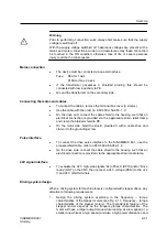
Notice:
In order to ensure the common grounding between SINUMERIK 801 CNC and
PC, use only shielded cable and make sure that the shield is connected to the
metal or metal plated connector casing on both ends of the cable.
Connect and disconnect cables between CNC and PC under power-off
conditions only;
We recommend you to use a RS232 terminal adapter (order number:
6FX2003-0DS00).
!
Summary of Contents for Sinumerik 801
Page 1: ...Start Up 11 2005 Edition sinumerik SIEMENS SINUMERIK 801 ...
Page 6: ......
Page 8: ......
Page 16: ......
Page 78: ......
Page 81: ...Services Diagnosis and Data Saving SINUMERIK 801 5 3 Start Up Fig 5 4 ...
Page 105: ...A5E00702069 ...


