Installing the Control System
2.3
Connecting the individual components
2-26
SINUMERIK 802C
6FC5 597–3AA20–0BP2 (01.02)
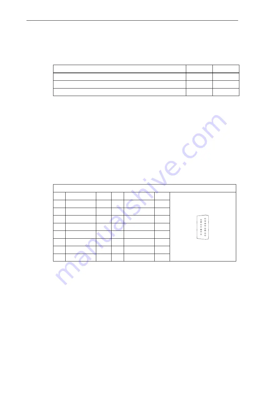
Relay contact
Table 2-6
Electrical parameters of the relay contacts RFn.1 and RFn.2
Parameter
Max.
Unit
Switching voltage
50
V
Switching current
1
A
Switching power
30
VA
Cable length: max. 35 m
2.3.3
Connecting the measuring systems (X3 ... X6)
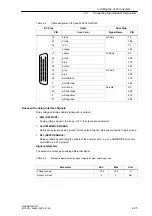
Pin assignment of the connector on the ENC side
Measuring system interface (incremental encoder)
Connector designation:
X3 ... X6
ENCODER
Connector type:
15–pin sub–D plug connector
Table 2-7
Pin assignment of the female connector X3 ... X6
X3 ... X6
Pin
Signal
Type
Pin
Signal
Type
1
9
M
VO
2
10
N
I
3
11
N_N
I
8
4
P5_MS
VO
12
B_N
I
15
5
VO
13
B
I
1
9
6
P5_MS
VO
14
A_N
I
7
M
VO
15
A
I
8
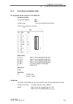
Signal names
A, A_N
Track A (true and negated)
B, B_N
Track B (true and negated)
N, N_N
Zero mark (true and negated)
P5_MS
+5.2 V supply
M
Supply ground
Signal level
RS422
Signal type
VO
Voltage output (supply)
I
5V input (5V signal)
Summary of Contents for SINUMERIK 802C
Page 1: ...Start Up 01 2002 Edition SINUMERIK 802C ...
Page 2: ......
Page 8: ...Table of Contents viii SINUMERIK 802C 6FC5 597 3AA20 0BP2 01 02 notice ...
Page 40: ...Installing the Drives 3 40 SINUMERIK 802C 6FC5 597 3AA20 0BP2 01 02 ...
Page 138: ...Index Index 138 SINUMERIK 802C 6FC5 597 3AA20 0BP2 01 02 notice ...
Page 140: ......


