Connecting
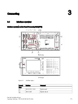
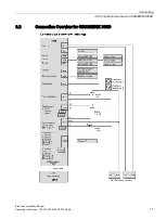
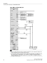
3.3 Connecting the interfaces on the PPU
Electrical Installation Manual
Operating Instructions, 12/2014, 6FC5397-2EP10-0BA0
23
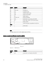
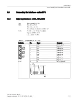
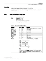
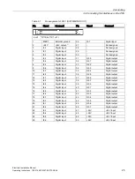
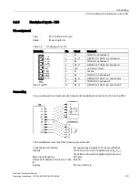
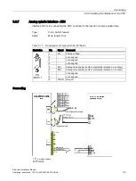
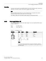
Table 3- 6
Pin assignment of X21 (FAST I/O)
Illustration
Pin
Signal
Comment
1
+24 V
+24 V input (20.4 - 28.8 V)
2
NCRDY_1
NCRDY contact 1
3
NCRDY_2
NCRDY contact 2
4
DI1
Digital input
5
DI2
Digital input
6
BERO_SPINDLE or DI3
Spindle bero or digital input
7
DO1
Fast output
8
CW
Spindle rotating clockwise
9
CCW
Spindle rotating counter-clockwise
10
M
Ground
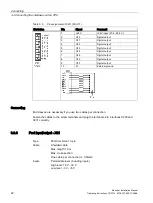
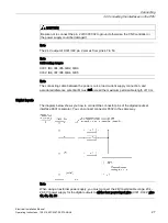
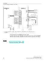
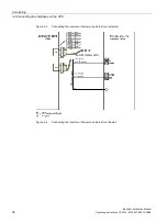
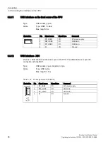
Connecting
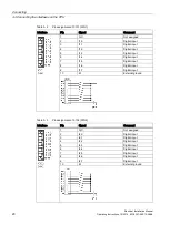
You can connect the FAST I/O to the inverter to control the spindle rotating direction
(unipolar):
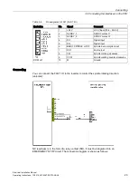
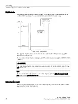
NC readiness is in the form of a relay contact (NO). It must be integrated into an
EMERGENCY STOP circuit. The connection diagram is shown as follows:


