Connecting
3.3 Connecting the interfaces on the PPU
Electrical Installation Manual
Operating Instructions, 12/2014, 6FC5397-2EP10-0BA0
31
Connecting
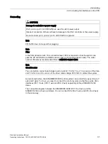
CAUTION
Damage to controller or power supply
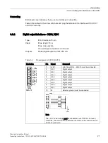
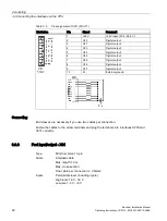
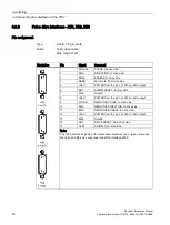
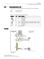
Pin 5, pin 8 or pin 12 of X51/52/53 are used for +24V power output.
Incorrect connection of them will lead to damage to the CNC controller or the power supply.
Do not connect pin 5, pin 8 or pin 12 of X51/52/53 to ground.
Note
X51/52/53 does not support hot plugging.
Note
Filter
A line filter (rated current: 16 A, protection level: IP20) is required so that the system can
pass the CE certification (radiated emission test or conducted emission test). The order
number of Siemens recommended filter is 6SN1111-0AA01-1BA1.
Note
Circuit breaker
You can install a mains linear breaker (rated current: 15 A for 7 A or 10 A version of the drive
and 10 A for 4 A or 6 A version of the drive; rated voltage: 250 VAC) to protect the system.
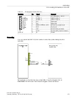
As mentioned before, the SINUMERIK 808D control system can control three axes (X axis, Y
axis and Z axis). To do so, you need to connect the control system via the three pulse drive
interfaces (X51: X axis, X52: Y axis and X53: Z axis) separately to three SINAMICS V60
drives.
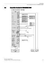
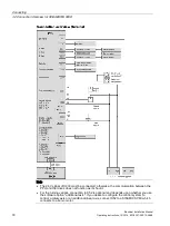
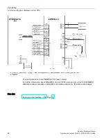
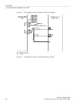
The connection diagram between the SINUMERIK 808D (X51: the X axis) and the
SINAMICS V60 is shown as follows. You can connect X52 (the Y axis) and X53 (the Z axis)
in the same way.

