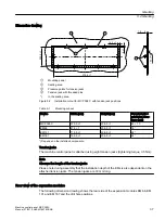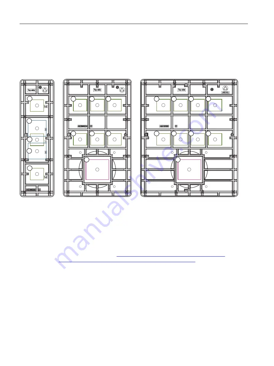
Observe the dimensions of your switching elements to be installed:
● Installation locations for switching elements d = 16 mm are suitable for compact switching
elements.
● Installation locations for switching elements d = 16/22 mm are suitable for larger switching
elements.
(0
(0
(0
①
Installation location for switching elements d = 16/22 mm
②
Installation location for switching elements d = 16 mm
③
Installation location for override switch/handwheel or another operator control
Figure 5-3
Rear view of the EMs 66, 131 and 187 with installation suggestions for the switching elements
You can find additional information in the DT configurator on the Internet at: https://
w3.siemens.com/drives/global/en/engineering-commissioning-software/dt-configurator/
Pages/dt-configurator.aspx (
https://w3.siemens.com/drives/global/en/engineering-
commissioning-software/dt-configurator/Pages/dt-configurator.aspx
Mounting position
Max. 45° to the vertical For mounting positions greater than 45°, a fan must also be installed
to keep the ambient temperature of the machine control panel constantly below 55° C.
Mounting
5.2 Mounting
Machine control panel: MCP 398C
38
Manual, 07/2018, A5E43199783B AB
Summary of Contents for SINUMERIK 840 sl
Page 26: ...Description 2 4 Rating plate Machine control panel MCP 398C 26 Manual 07 2018 A5E43199783B AB ...
Page 34: ...Dimension drawings Machine control panel MCP 398C 34 Manual 07 2018 A5E43199783B AB ...
Page 66: ...Safety symbols Machine control panel MCP 398C 66 Manual 07 2018 A5E43199783B AB ...
Page 68: ...Index Machine control panel MCP 398C 68 Manual 07 2018 A5E43199783B AB ...


