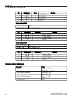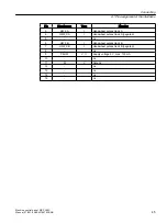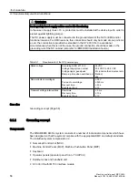
Technical data for digital outputs
Parameter
Value
Voltage
1)
24 V (20.4 V ... 28.4 V)
Maximum load current per output
0.5 A
Maximum load current per connector
1 A
Maximum load current per output at 100% simul‐
taneity of all six outputs
0.15 A
Electrical isolation
None
1) Supplied directly via connector X10
6.1.6
Handwheels
Handwheel 1
Connector designation: X60
Connector type:
15-pin Sub-D socket
Pin
Signal name
Type
Meaning
1
P5HW
V, O
Supply voltage 5 V, max. 100 mA
2
M
V
Ground
3
HW1_A
I
Handwheel pulses track A
4
HW1_XA
I
Handwheel pulses track A (negated)
5
-
n.c.
6
HW1_B
I
Handwheel pulses track B
7
HW1_XB
I
Handwheel pulses track B (negated)
8
-
n.c.
9
P5HW
V, O
Supply voltage 5 V, max. 100 mA
10
-
n.c.
11
M
V
Ground
12
-
n.c.
13
-
n.c.
14
-
n.c.
15
-
n.c.
Handwheel 2
Connector designation: X61
Connector type:
15-pin Sub-D socket
Pin
Signal name
Type
Meaning
1
P5HW
V, O
Supply voltage 5 V, max. 100 mA
2
M
V
Ground
Connecting
6.1 Pin assignment of the interfaces
Machine control panel: MCP 398C
44
Manual, 07/2018, A5E43199783B AB
Summary of Contents for SINUMERIK 840 sl
Page 26: ...Description 2 4 Rating plate Machine control panel MCP 398C 26 Manual 07 2018 A5E43199783B AB ...
Page 34: ...Dimension drawings Machine control panel MCP 398C 34 Manual 07 2018 A5E43199783B AB ...
Page 66: ...Safety symbols Machine control panel MCP 398C 66 Manual 07 2018 A5E43199783B AB ...
Page 68: ...Index Machine control panel MCP 398C 68 Manual 07 2018 A5E43199783B AB ...


