Ethernet communication
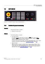
7.5 MCP 483C IE
Manual
194
Commissioning Manual, 05/2008, 6FC5397–4CP10–4BA0
Display of the IP address
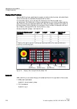
After the MCP has been electrically connected, all LEDs on the front side of the MCP flash
until communication is established between MCP and PLC.
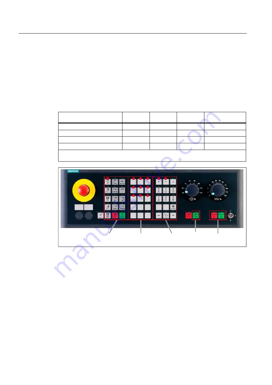
To activate the display you must press the "Feed stop" and "Feed enable" keys
simultaneously. The Version No. of the current software version is then displayed with the
help of the continuously illuminated LEDs first. Press the "Enable spindle" key to switch to
the four positions of the IP address. One position of the IP address is displayed with each
key actuation, starting with the one having the max. value.
Example default IP address: 192.168.214.192
Pressing the "Spindle enable"
key n times
1. digit
1)
2. Digit
1)
3. Digit
1)
Digit of the IP
address
1
1
9
2
1
2
1
6
8
2
3
2
1
4
3
4
1
9
2
4
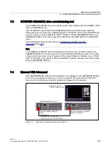
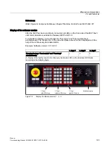
1) Display of the digit by means of continuously illuminated LEDs on the individual LED blocks
according to the following figure
VWGLJLW
OHIW/('%ORFN
QGGLJLW
FHQWHU/('%ORFN
UGGLJLW
ULJKW/('%ORFN
7UDQVLWLRQ
$FWLYDWHGLVSOD\
Figure 7-6
Display of the 1st digit of the IP address: 192
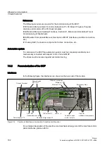
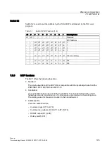
Switch S1
With switch S1 you can select the type of handwheel that is to be operated on the module:
●
Differential handwheels
Switch S1 closed (delivery state)
●
TTL handwheels
Switch S1 open

