Drive commissioning (SINAMICS)
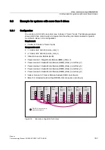
9.3 Example for systems with more than 6 drives
Manual
334
Commissioning Manual, 05/2008, 6FC5397–4CP10–4BA0
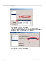
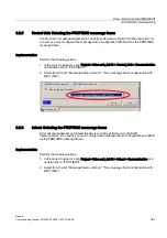
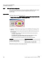
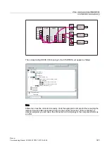
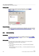
Creating a project
The project should be created according to the description in Chapter "ONLINE-
Startup" (Page 309). Both drive units must be displayed in the preview window.
$QWULHEVJHU¦WB$GU
$QWULHEVJHU¦WB$GU
3URMHNW
=XU¾FN
$EEUHFKHQ
=XVDPPHQ
IDVVXQJ
$QWULHEV
JHU¦W
HLQI¾JHQ
3*3&
6FKQLWWVWHOOH
HLQVWHOOHQ
1HXHV3URMHNW
HUVWHOOHQ
(LQI¾KUXQJ
:HLWHU!
$QVLFKW
DNWXDOLVLHUHQ
67$57(53URMHNWDVVLVWHQW
9RUVFKDX
Figure 9-6
STARTER: Project Wizard (excerpt)
Component topology
The automatic entry of the component topology and configuration is to be done according to
Chapter "Drive unit: Enter component topology and configuration automatically" (Page 316)
for each drive unit.
9.3.2
Basic commissioning
Commissioning
The startup of the drive components is to be undertaken according to the Chapter "Drive:
Configuring motors and encoders" (Page 318) given above to Chapter "Drive: Running the
Infeed: operation
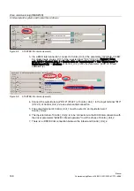
The parameter "p864, BI: Infeed operation" of all drives is to be connected with the
corresponding signal of infeed "r863: Bit0, infeed operation".
●
Control_Unit_1
Drives controlled by Control_Unit_1 (Drive_1..._5) are interconnected automatically.
●
Control_Unit_2
Drives controlled by Control_Unit_2 (Drive_6..._9) must be manually interconnected (see
the following chapter).

