NC Commissioning with HMI Advanced
11.5 Axes and spindles
Manual
394
Commissioning Manual, 05/2008, 6FC5397–4CP10–4BA0
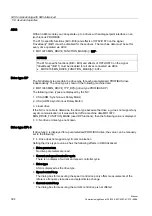
NOTICE
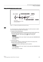
The motor measuring system is always used for the speed control function. Motor and
motor measuring system must therefore always be connected to the same drive module.
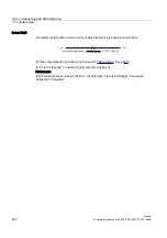
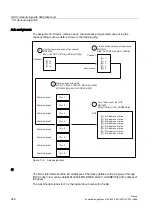
In the two following axis-specific machine data, the same logical drive number m of the drive
is entered that the machine axis represents:
●
MD30110 $MA_CTRLOUT_MODULE_NR[0] (setpoint assignment: logical drive number)
●
MD30220 $MA_ENC_MODUL_NR[n] (actual value assignment: logical drive number)
The entered value m refers to the drive whose I/O address is defined under the index n = (m-
1) in MD13050 $MN_DRIVE_LOGIC_ADDRESS[n] (see Chapter "Drive
NC reset
Once the drive configuration and setpoint/actual value assignment have been parameterized,
an NC reset must be executed to initiate a warm restart of the NC. After the NC has powered
up, the set configuration is effective.
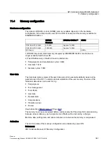
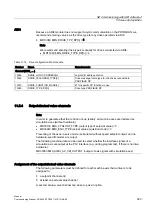
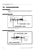
Measuring system switchover
The following interface signals can be used to switch between the two position measuring
systems of a machine axis from the PLC.
●
DB31, ... DBX1.5 (position measuring system 1 selected)
●
DB31, ... DBX1.6 (position measuring system 2 selected)
References:
/FB1/ Function Manual - Basic Functions, A2 various Interface Signals
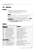
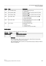
Machine data
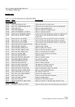
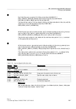
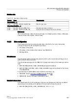
Table 11-17 Setpoint/actual value channels: Machine data
Number
Name
Name/remarks
Axisspecific ($MA_ ... )
30100
CTRLOUT_SEGMENT_NR
Setpoint assignment: Drive type
5 = PROFIBUS DP
30110
CTRLOUT_MODULE_NR
Setpoint assignment: Logical drive number
30130
CTRLOUT_TYPE
Output type of setpoint
0 = simulation
1 = speed setpoint output
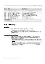
30200
NUM_ENCS
Number of measurement channels
1 = one position measuring system installed
2 = two position measuring systems installed

