NC Commissioning with HMI Advanced
11.5 Axes and spindles
Manual
Commissioning Manual, 05/2008, 6FC5397–4CP10–4BA0
403
Parameter example
The following parameterization example illustrates the basic procedure for parameterizing
the NC for a 2nd measuring system of a machine axis connected via ADI4. It assumes the
following:
●
NC
Two measuring systems are to be parameterized for the 1st machine axis.
–
1. Measuring system: "motor measuring system" of the drive
–
2. Measuring system: "direct measuring system"
●
Drive
A SIMODRIVE 611U 1 axis module is used as the drive with a connection option for a
measuring system (motor encoder).
●
ADI4
The 2nd measuring system is connected via the encoder interface of the 1st axis of an
ADI4 module. (In principle, connection is possible via any axis of the ADI4 module.)
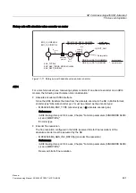
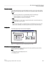
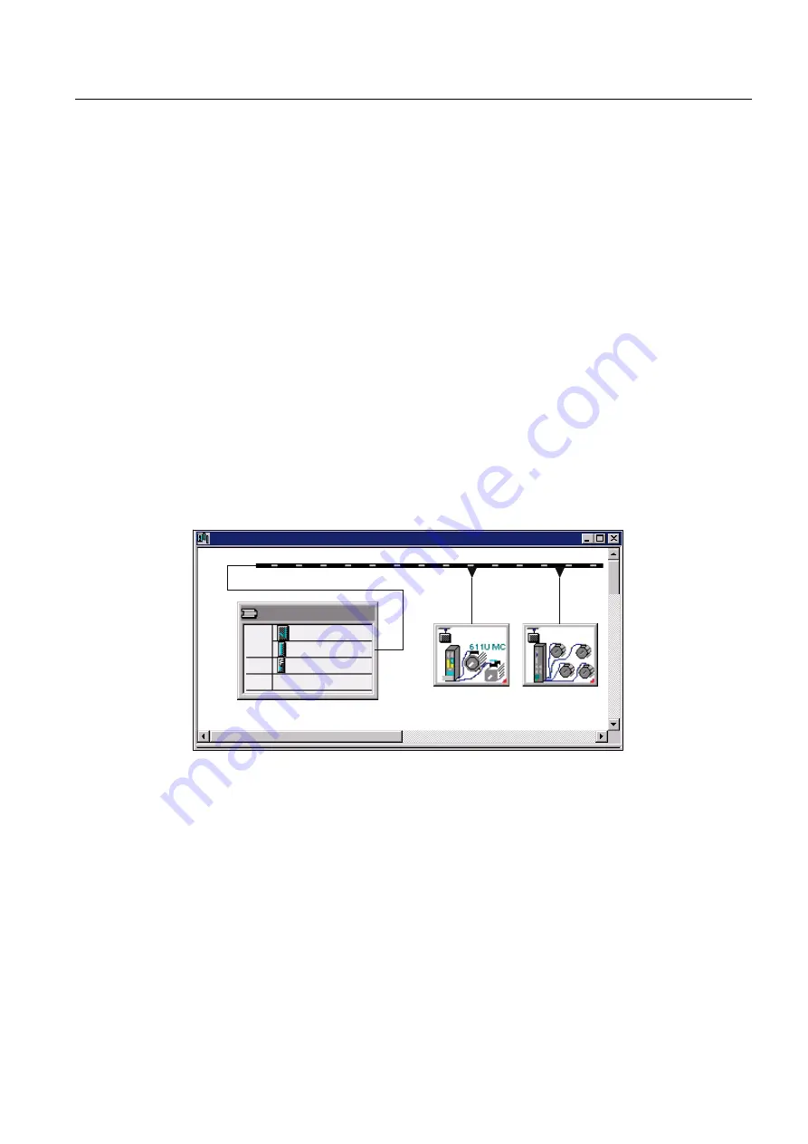
Configuration
The following figure shows the associated configuration.
6)01&8
3/&'3
'LVO
$',
6,02'
'3PDVWHU
;
'LVOFRQILJXUDWLRQ8B$',
352),%86'3PDVWHUV\VWHP
Figure 11-12 Configuration: Axis with 2nd measuring system on ADI4
I/O addresses and message frame types
The I/O addresses and message frame types for the drive and ADI4 axis are set to the
following values in the configuration:
Drive:
●
Message frame type: Message frame 102
●
I/O address: 4100

