NC Commissioning with HMI Advanced
11.5 Axes and spindles
Manual
432
Commissioning Manual, 05/2008, 6FC5397–4CP10–4BA0
t
3KDVH
3KDVH
3KDVH
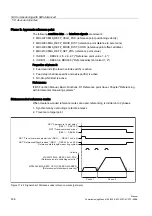
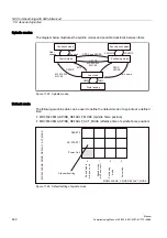
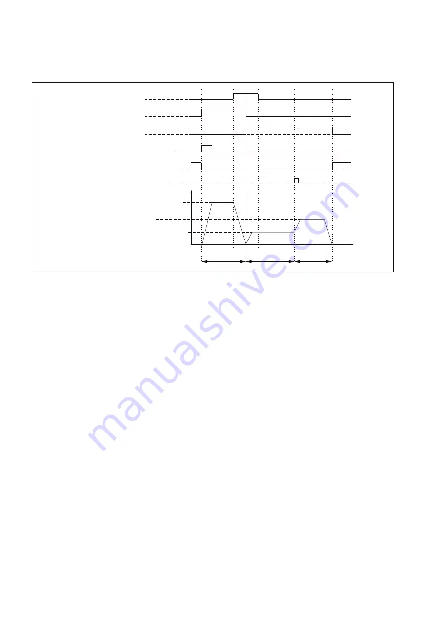
0'0$B5()3B9(/2B326
5HIHUHQFHSRLQWSRVLWLRQLQJYHORFLW\
0'0$B5()3B9(/2B6($5&+B0$5.(5
5HIHUHQFHSRLQWVKXWGRZQYHORFLW\
0'0$B5()3B9(/2B6($5&+B&$0
5HIHUHQFHSRLQWDSSURDFKYHORFLW\
9HORFLW\
167$SSURDFKUHISRLQWGHOD\
'%'%;
1677UDYHOFRPPDQGSOXV
'%'%;
1677UDYHOFRPPDQGPLQXV
'%'%;
1677UDYHOFRPPDQGSOXVPLQXV
'%'%;XQG
1675HIHUHQFHGV\QFKURQL]HG
'%'%;XQG
=HURPDUNSRVLWLRQLQJPHDVXUHPHQW
V\VWHP
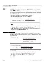
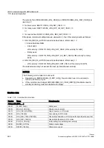
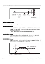
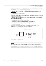
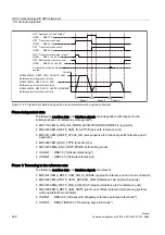
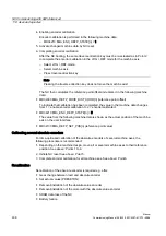
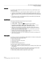
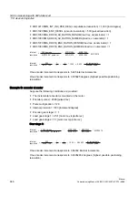
Figure 11-23 Signal chart: Referencing with an incremental measuring system (principle)
Phase-independent data
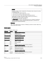
The following machine data and interface signals are independent with respect to the
individual phases of reference point approach:
●
MD11300 $MN_JOG_INC_MODE_LEVELTRIGGRD (INC/REF in jog mode)
●
MD34000 $MA_REFP_CAM_IS_ACTIVE (axis with reference cam)
●
MD34110 $MA_REFP_CYCLE_NR (axis sequence for channel-specific reference point
approach)
●
MD30240 $MA_ENC_TYPE (encoder type)
●
MD34200 $MA_ENC_REFP_MODE (referencing mode)
●
IS DB21, ... DBX1.0 ("Activate referencing")
●
IS DB21, ... DBX33.0 ("Activate referencing")
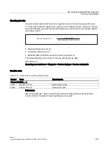
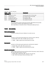
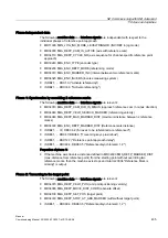
Phase 1: Traversing to the reference cam
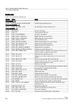
The following machine data and interface signals are relevant:
●
MD34010 $MA_REFP_CAM_DIR_IS_MINUS (approach reference cam in minus direction)
●
MD34020 $MA_REFP_VELO_SEARCH_CAM (Reference cam approach velocity)
●
MD34030 $MA_REFP_MAX_CAM_DIST (maximum distance to the reference cam)
●
MD34092 $MA_REFP_CAM_SHIFT (electr. cam offset, incremental measuring systems
with equidistant zero markers)
●
IS DB21, ... DBX36.2 ("All axes with obligatory reference point are referenced")
●
IS DB31, ... DBX4.7/DBX4.6 ("Traversing keys plus/minus")

