NC Commissioning with HMI Advanced
11.5 Axes and spindles
Manual
434
Commissioning Manual, 05/2008, 6FC5397–4CP10–4BA0
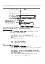
Phase 3: Approach reference point
The following machine data and interface signals are relevant:
●
MD34070 $MA_REFP_VELO_POS (reference point positioning velocity)
●
MD34080 $MA_REFP_MOVE_DIST (reference point distance to zero mark)
●
MD34090 $MA_REFP_MOVE_DIST_CORR (reference point offset, additive)
●
MD34100 $MA_REFP_SET_POS (reference point value)
●
IS DB31, ... DBX2.4, 2.5, 2.6, 2.7 ("Reference point value 1...4")
●
IS DB31, ... DBX60.4, DBX60.5 ("Referenced/synchronized 1, 2")
Properties of phase 3:
●
Feed override (the feed override switch) is active.
●
Feed stop (channel-specific and axis-specific) is active.
●
NC-Stop/NC start is active.
References:
/FB1/ Function Manual, Basic Functions, R1 Reference point travel, Chapter "Referencing
with incremental measuring systems"
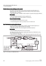
Distancecoded reference marks
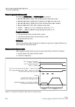
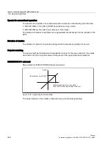
When clearance-coded reference marks are used, referencing is divided into 2 phases:
1.
Synchronize by overriding 2 reference marks
2.
Traverse to target point
W
3KDVH
3KDVH
0'0$B5()3B9(/2B326
5HIHUHQFHSRLQWSRVLWLRQLQJYHORFLW\
0'0$B5()3B9(/2B6($5&+B0$5.(5
5HIHUHQFHSRLQWVKXWGRZQYHORFLW\
9HORFLW\
167$SSURDFKUHISRLQWGHOD\
'%'%;
1677UDYHOFRPPDQGPLQXV
'%'%;
1677UDYHOFRPPDQGSOXVPLQXV'%'%;XQG
1675HIHUHQFHG6\QFKURQL]HG'%'%;XQG
5HIHUHQFHPDUNOHQJWKPHDVXULQJV\VWHP
Figure 11-24 Signal chart: Distance-coded reference marks (principle)

