NC Commissioning with HMI Advanced
11.7 Digital and analog I/O devices
Manual
Commissioning Manual, 05/2008, 6FC5397–4CP10–4BA0
475
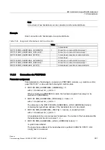
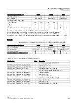
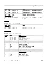
Slot
Assembly
I address
O address
Comment
Note:
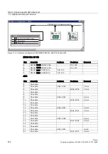
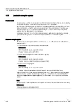
The structure of the PROFIBUS message frame is described in Chapter "DP Slave:
Machine data
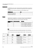
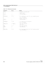
Parameterization of the NC machine data is shown below:
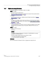
ET 200
3 input bytes
ADI4
1 input byte
Note
Although only 4 input bytes are used, 5 must be declared. The 1st input byte is always
assigned to the MCI board extension module even if it is not installed:
●
MD10350 $MN_FASTIO_DIG_NUM_INPUTS = 5
Number of output bytes
ET 200
2 output bytes
ADI4
2 output bytes
Note
Although only 4 output bytes are used, 5 must be declared. The 1st output byte is always
assigned to the MCI board extension module even if it is not installed:
●
MD10360 $MN_FASTIO_DIG_NUM_OUTPUTS = 5
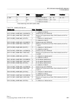
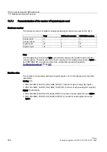
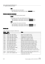
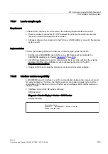
Hardware assignment: input bytes
The following input bytes are used by the NC:
●
ET 200
Both input bytes of the input module (slot 6)
–
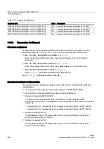
MD10366 $MN_HW_ASSIGN_DIG_FASTIN[0] = H05000080 (128
D
)
–
MD10366 $MN_HW_ASSIGN_DIG_FASTIN[1] = H05000081 (129
D
)
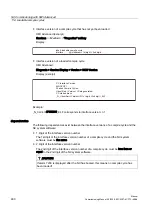
The 4th of the 4 input bytes of the signal module (slot 7)
–
MD10366 $MN_HW_ASSIGN_DIG_FASTIN[2] = H05000085 (133
D
)

