Drive Optimization with HMI Advanced
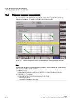
14.4 Frequency response measurements
Manual
514
Commissioning Manual, 05/2008, 6FC5397–4CP10–4BA0
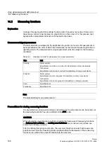
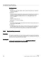
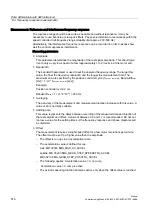
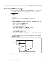
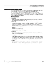
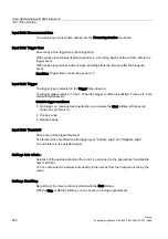
Measuring parameters
●
Amplitude
Magnitude of the test signal amplitude. Given in percent of the peak torque. Values from
1% to 5% are suitable.
●
Bandwidth
The frequency range analyzed with the measurement. The larger this value, the finer the
frequency resolution and the longer the measurement time. The maximum value is
specified by the position controller cycle (T
position controller
): Bandwidth
max
[Hz] = 1 / (2 *
T
position controller
[sec])
Example:
Position controller cycle: 2 ms
Bandwidth
max
= 1 / (2 * 2*10
-3
) = 250 Hz
●
Averaging
The accuracy of the measurement and measurement duration increase with this value. A
value of 20 is normally suitable.
●
Settling time
This value represents the delay between recording of the measured data and injection of
the test setpoint and offset. A value of approx. 10 ms is recommended. A settling time
which is too low will result in frequency response and phase diagrams distortions.
14.4.2
Speed control loop measurement
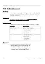
Functionality
The response characteristics for the motor measuring system are analyzed when measuring
the speed control loop. Various measurement parameter lists are available depending on the
basic measurement setting which has been selected.
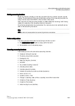
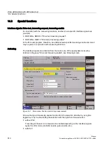
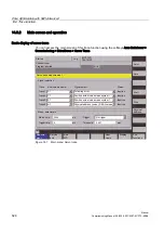
Operating path
Operating path for measuring the speed control loop: Operating area switchover >
Commissioning > Optimization/Test > Speed control loop

