Drive Optimization with HMI Advanced
14.4 Frequency response measurements
Manual
Commissioning Manual, 05/2008, 6FC5397–4CP10–4BA0
519
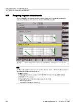
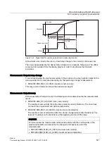
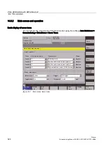
Measurement: Reference frequency response
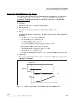
The reference frequency response measurement determines the transmission ratio of the
position controller in the frequency range (active position measuring system).
The setpoint filters, control loop gain (K
v
factor) and feedforward control must be
parameterized such that resonance is avoided wherever possible over the entire frequency
range. In the case of dips in the frequency response, the setting of the feedforward control
balancing filters should be checked.
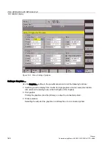
Measuring parameters
●
Amplitude
This parameter determines the magnitude of the test signal amplitude. It should be set to
the smallest possible value (e.g. 0.01 mm).
●
Bandwidth
The bandwidth parameter is used to set the analyzed frequency range. The larger this
value, the finer the frequency resolution and the longer the measurement time. The
maximum value is specified by the position controller cycle (T
position controller
): Bandwidth
max
[Hz] = 1 / (2 * T
position controller
[sec])
Example:
Position controller cycle: 2 ms
Bandwidth
max
= 1 / (2 * 2*10
-3
) = 250 Hz
●
Averaging
The accuracy of the measurement and measurement duration increase with this value. A
value of 20 is normally suitable.
●
Settling time
This value represents the delay between recording of the measured data and injection of
the test setpoint and offset. A value of between 0.2 and 1 s is recommended. Do not set
too low a value for the settling times or the frequency response and phase diagrams will
be distorted.
●
Offset
The measurement requires a slight speed offset of a few motor revolutions per minute.
The offset must be set such that no speed zero crossings occur at the set amplitude.

