Hardware Descriptions
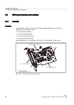
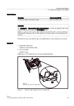
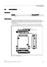
2.4 Cable distributor
Manual
66
Commissioning Manual, 05/2008, 6FC5397–4CP10–4BA0
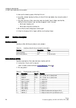
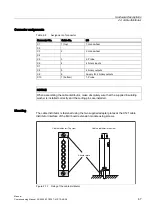
Insert the appropriate individual cable in the opened cable distributor at the associated
connector X1 to X10. Place the cable in the appropriate cable guide.
Make sure that the shield jackets that became free have a large conductive connection to the
metallic contact areas of the cable distributor. See the following figure for this purpose. Insert
the upper terminal bar in such a way that its "teeth" are facing the "teeth" of the lower
terminal bar and then secure the upper housing section.
This will reliably press the cable shields between the contact areas of the contact springs
and contact them safely. The shield potential is reliably routed to the housing of the PCU
using the contact springs of the cable distributor on the front panel of the PCU.
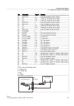
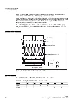
Location of the interfaces
&DEOH,QOHWV
7HUPLQDOFDSV
&RQWDFWVXUIDFHV
3OXJLQFRQQHFWRUV;;
6ELV6
RSHQ
FORVHG
6XE'VRFNHWFRQQHFWRU
;
;
;
;
;
;
;
;
;
;
;
6
6
6
6
6
6
Figure 2-11 Position of the interfaces of the cable distributor
DIP FIX switches
The DIP FIX switches in the cable distributor must be set as follows:
Table 2-8
Setting the DIP-FIX switches in the cable distributor
switch
S1
S2
S3
S4
S5
S6
Open
x
x
x
x
Closed
x
x

