Hardware Descriptions
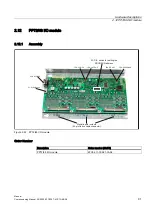
2.12 PP72/48 I/O module
Manual
Commissioning Manual, 05/2008, 6FC5397–4CP10–4BA0
95
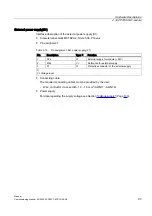
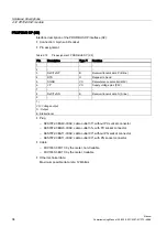
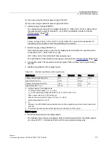
PROFIBUS address (S1)
The PROFIBUS address of the ADI4 can be set in the range 1 to 127 using switch S1.
Table 2-16 Meaning of switch S1
switch
Description
1
PROFIBUS address: 2
0
= 1
2
PROFIBUS address: 2
1
= 2
3
PROFIBUS address: 2
2
= 4
4
PROFIBUS address: 2
3
= 8
5
PROFIBUS address: 2
4
= 16
6
PROFIBUS address: 2
5
= 32
7
PROFIBUS address: 2
6
= 64
8
Not used
NOTICE
A newly set PROFIBUS address will only come into effect after power OFF/ON.
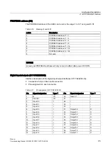
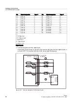
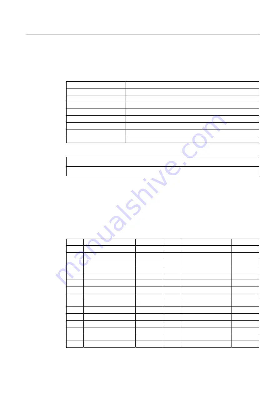
Digital inputs/outputs (X111/X222/X333)
Interface description of the digital input/output interfaces (X111/X222/X333):
●
Connectors: 50-pin ribbon cable connector
●
Pin assignment on each connector.
Table 2-17 Pin assignment (X111/X222/X333)
Pin
Signal designation
Type
1)
Pin
Signal designation
Type
1)
1
M
VO
26
Input 2.7
I
2
P24OUT
VO
27
-
-
3
Input 0.0
I
28
-
-
4
Input 0.1
I
29
-
-
5
Input 0.2
I
30
-
-
6
Input 0.3
I
31
Output 0.0
O
7
Input 0.4
I
32
Output 0.1
O
8
Input 0.5
I
33
Output 0.2
O
9
Input 0.6
I
34
Output 0.3
O
10
Input 0.7
I
35
Output 0.4
O
11
Input 1.0
I
36
Output 0.5
O
12
Input 1.1
I
37
Output 0.6
O
13
Input 1.2
I
38
Output 0.7
O
14
Input 1.3
I
39
Output 1.0
O
15
Input 1.4
I
40
Output 1.1
O

