Ethernet communication
7.7 HT 2
Manual
Commissioning Manual, 05/2008, 6FC5397–4CP10–4BA0
223
7.7.2
Linking to the basic PLC and user program
7.7.2.1
Interface signals
Number system
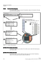
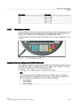
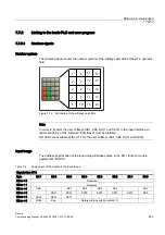
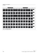
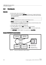
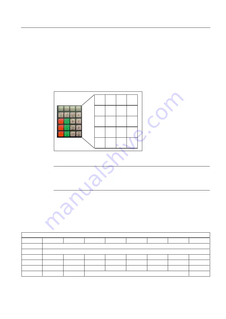
The following figure shows the number system of the softkeys and LED of the HT 2 operator
field.
Figure 7-12 Numbering of the softkeys and LEDs
Note
In order to transfer the user softkeys (SK1, SK6, SK11 and SK16) in the input interface, at
least version 8.2 of the software "PCU-Base" must be installed.
NO LEDs are available at the HT 2 for the user softkeys (SK1, SK6, SK11 and SK16).
Input image
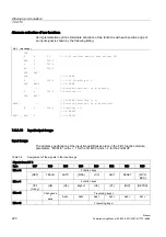
The address specification of the input image EB takes place in the FB 1 function module,
parameters: "HHUIn".
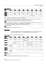
Table 7-8
Assignment of the signals in the input image
Signals from HT 2
Byte
Bit 7
Bit 6
Bit 5
Bit 4
Bit 3
Bit 2
Bit 1
Bit 0
EB m + 0
Reserved
EB m + 1
Reserved
EB m + 2
SK8
-
SK7
SK5
SK4
SK3
-
SK2
EB m + 3
-
SK12
SK20
SK19
SK18
SK17
SK10
SK9
EB m + 4
SK25
SK14
SK13
-
-
-
-
-
EB m + 5
Write
Key-
Rotary coding switch (override) 1)
-

