PROFIBUS DP Communication
8.4 SIMATIC I/O devices (ET200...)
Manual
Commissioning Manual, 05/2008, 6FC5397–4CP10–4BA0
249
8.3.5
Load the configuration in the PLC
The configuration can be loaded in the PLC after generating the system data module
successfully.
Loading the configuration is descried in detail within the framework of the PLC
commissioning in Chapter "Load configuration (STEP 7 -> PLC)" (Page 179).
8.3.6
PROFIBUS diagnosis
The following diagnostic displays are recommended for diagnosing the PROFIBUS or DP
slave status while checking the configuration or if errors occur.
●
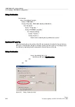
840Di startup
Menu bar: Window > Diagnosis > Profibus > Bus or slaves
●
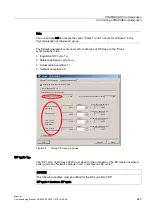
HMI Advanced
Operating area switchover > Diagnosis > Service displays > "ETC" key > Profibus
Diagnosis
8.4
SIMATIC I/O devices (ET200...)
The SIMATIC I/O devices of the Production Series ET200, e.g. ET200M, are brought into the
S7 project as usual, and configured.
Note
To simplify the parameterization of equidistant communication at PROFIBUS DP, all the
required SIMATIC I/O devices must first be added in the configuration before parameterizing
the DP drives (e.g. DP slave 611 U or ADI4).
Note
To check whether a module selected from the hardware catalog complies with the module in
the automation system, the following procedure is recommended:
1.
Note the MLFB numbers of all modules used in the automation system.
2.
Select the corresponding module in the hardware catalog and compare the MLFB
number of the module used in the automation system with the MLFB number that is
displayed in the hardware catalog. Both MLFB numbers must be the same.

