NC Commissioning with HMI Advanced
11.7 Digital and analog I/O devices
Manual
Commissioning Manual, 05/2008, 6FC5397–4CP10–4BA0
471
11.7.4
Digital input/output bytes and system variables
Digital inputs
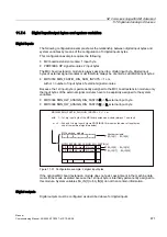
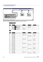
The following configuration example shows the relationship between digital input bytes and
system variables by means of the configuration of 3 digital inputs bytes.
This configuration example requires the following:
●
MCI board extension module: 1 input byte
●
PROFIBUS DP signal modules: 2 input bytes
The MCI board extension module is always assigned to a digital input byte. Digital input
bytes of external signal modules must therefore always be counted as additional input bytes:
●
MD10350 $MN_FASTIO_DIG_NUM_INPUTS = 1 + m,
with m = number of input bytes of external signal modules
Because the 1st input byte is permanently assigned to the MCI board extension module, only
the input bytes of the external signal modules have to be explicitly assigned to the system
variables.
●
MD10366 $MN_HW_ASSIGN_DIG_FASTIN[0] -> 1. external input byte
●
MD10366 $MN_HW_ASSIGN_DIG_FASTIN[1] -> 2. external input byte
Q
0'01B)$67,2B',*B180B,13876 P
ZLWKൺVWGLJLQSXWE\WHRIWKH0&,ERDUGH[WHQVLRQPRGXOHDOZD\VVHHWH[W
P ൺQGDQGUGGLJLQSXWE\WHYLD352),%86,2PRGXOHVQXPEHURILQSXWE\WHV
XVHGIURPH[WHUQDOVLJQDOPRGXOHV
$B,1>@$B,1>@
$B,1>@$B,1>@
6\VWHPYDULDEOH
$B,1>@$B,1>@
($+LJK
($/RZ
0&,ERDUGH[PRGXOH
0'01B+:B$66,*1B',*B)$67,1>Q@
($+LJK
($/RZ
Figure 11-31 Configuration example: 3 digital input bytes
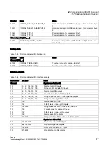
If the optional MCI board extension module does not exist, assignment in the machine data
must still be made as stated because the 1st input byte is internally permanently assigned to
this module. System variables $A_IN[1] to $A_IN[4] do not then contain information.
Digital outputs
Digital outputs must be configured as described above for digital inputs.

