06.03
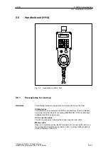
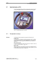
5.7 Handheld terminal HT 6
5-163
Siemens AG, 2003. All rights reserved
SINUMERIK 840Di Manual (HBI) – 06.03 Edition
Further references on the HT 6
/FBPH/
Description of Functions HT 6
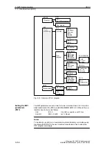
Configuring the HT 6 user interface
/IAM BE1/ Description of Functions HT 6
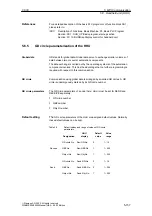
Completing the user interface
In order to start up the HT 6, the automation system must be electrically and
mechanically connected completely with respect to NC, PLC and HT 6.
The drives must be secured against accidental moving.
5.7.2
Parameterization of the HT 6
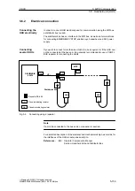
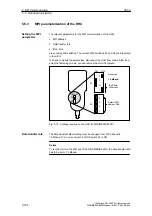
In order to connect HT 6 electrically and for the MPI communication, a distribu-
tor box is used.
Notice
Under no circumstances may the MPI connector for connecting the HT 6 be
enabled, since the HT 6 already contains an integrated bus terminator.
Please observe the warning notices with respect to the MPI cables and the
EMERGENCY STOP jumper. (For a detailed description, please refer to the
relevant references).
For a detailed description of the electrical and mechanical design of the distribu-
tor box, as well as for the electrical and data interfaces of the HT 6, please refer
to:
References:
/BH/
Operator Components, Manual
Section: Handheld Terminal HT 6
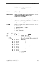
The HT 6 detects the data transfer rate at the MPI bus automatically. With the
SINUMERIK 840Di, it is 1.5 Mbaud.
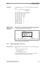
The factory-set MPI address of the HT 6 is 14 by 14
D
(D = decimal). The default
address can only be modified using the HT 6 system software.
The current software version of the HT 6 is displayed in a menu of the user in-
terface. After power-up of the HT 6, you will get to this menu using the following
sequence of operations:
1. Key MENU SELECT
2. Soft keys Diagnosis > Service display > Version > Vers. MMC.
Automation
system
Electrical
connection
Data transfer rate
MPI address
Display of the
software version
5 MPI Communication

