06.03
10.5 Axes and spindles
10-308
Siemens AG, 2003. All rights reserved
SINUMERIK 840Di Manual (HBI) – 06.03 Edition
10.5
Axes and spindles
10.5.1
Axis configuration
The term “axis” is often used either as a single term in conjunction with SINUM-
ERIK 840Di or as a compound, e.g. machine axis, channel axis, etc. To provide
an overview of the philosophy used as the basis, this term will be explained
here in brief.
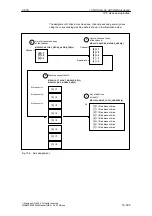
Generally, 3 types of axes are distinguished:
1. Coordinate axes
2. Machine axes
3. Geometry and special axes.
Coordinate axes (abscissa, ordinate, applicate) are the axes of a Cartesian
coordinate system.
Machine axes are the motion units existing on a machine, which can also be
designated as linear or rotary axes, depending on their useable movement.
The geometry and special axes serve to program traversing movements in
parts programs.
The total of all machine, geometry and special axes assigned to a channel is
designated as channel axes.
In this context, the geometry and special axes constitute the program-techno-
logical part of the machining process, i.e. they are used for programming in the
parts program.
The machine axes constitute the physical part of the machining process, i.e.
they carry out the programmed traversing movements on the machine.
The geometry axes constitute the rectangular Cartesian basic coordinate sys-
tem of a channel.
Generally, (Cartesian arrangement of the machine axes) direct imaging of the
geometry axes to the machine axes is possible. If the arrangement of the ma-
chine axes, however, is not Cartesian at right angles, the imaging is performed
using a kinematic transformation.
Additional axes are all other channel axes that are not geometry axes. Unlike
for geometry axes (Cartesian coordinate system), for additionalaxes, no geo-
metrical relation is defined, neither between special axes, nor with respect to the
geometry axes.
Definition
Coordinate
axes
Machine axes
Geometry and
special axes
Channel axes
Geometry axes
Additional axes
10 NC Start-Up with HMI Advanced

