06.03
10.5 Axes and spindles
10-352
Siemens AG, 2003. All rights reserved
SINUMERIK 840Di Manual (HBI) – 06.03 Edition
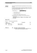
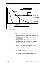
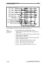
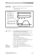
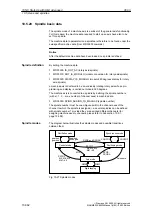
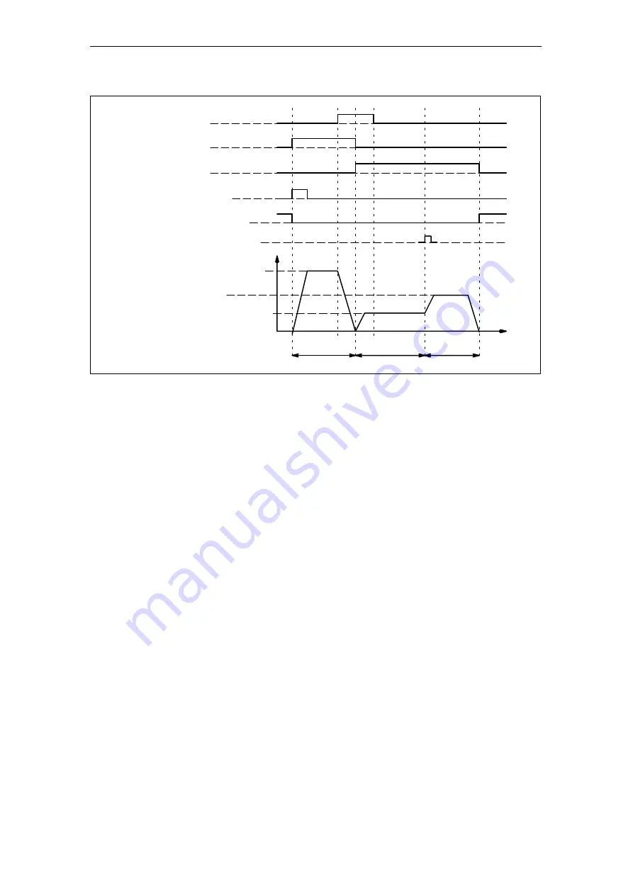
IS “Reference point approach delay”
(DB31, ... DBX12.7)
IS “Traversing command plus”
(DB31, ... DBX64.7)
IS “Traversing command minus”
(DB31, ... DBX64.6)
IS “Traversing key plus/minus”
(DB31, ... DBX4.7 and 4.6)
IS “Referenced/synchronized”
(DB31, ... DBX60.4 and 60.5)
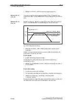
Zero marker of position
measuring system
Velocity
MD 34020: REFP_VELO_SEARCH_CAM
Reference-point approach velocity
MD 34040: REFP_VELO_SEARCH_MARKER
Reference-point shutdown velocity
MD 34070: REFP_VELO_POS
Reference-point positioning velocity
Phase 2
Phase 1
Phase 3
t
Fig. 10-25 Referencing sequence with incremental measuring system (example)
The following machine data and interface signals are important:
MD34010: REFP_VELO_SEARCH_CAM (reference cam approach in the
negative direction)
MD34020: REFP_VELO_SEARCH_CAM (reference cam approach velocity)
MD34030: REFP_MAX_MARKER_DIST
(maximum distance to reference cam)
MD 34092: REFP_CAM_SHIFT (electr. cam offset, incremental measuring
systems with equidistant zero markers)
IS: DB21, ... DBX36.2 (“All axes to be referenced are referenced”
IS: DB31, ... DBX4.7/DBX4.6 (“Traversing keys plus/minus”)
IS: DB31, ... DBX12.7 (“Reference point approach delay”)
IS: DB31, ... DBX60.4, DBX60.5 (“Referenced/synchronized 1, 2”).
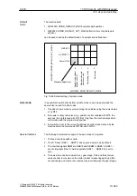
Phase 1:
Traversing to the
reference cam
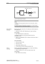
10 NC Start-Up with HMI Advanced

