06.03
10.5 Axes and spindles
10-353
Siemens AG, 2003. All rights reserved
SINUMERIK 840Di Manual (HBI) – 06.03 Edition
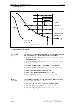
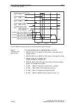
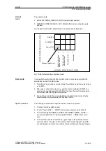
Properties of phase 1:
The feed override (the feed override switch) is active
The feed stop (channel-specific and axis-specific) is active
The machine axis can be stopped and started again using NC Stop/NC Start
If the machine axis traverses a distance defined in
MD 34030: REFP_MAX_CAM_DIST
(max. distance to the reference cam)
without reaching the reference cam
– IS: DB31, ... DBX12.7 (“Reference point approach delayed”) = 0
the axis stops, and
– alarm 20000 “Reference cam not reached”
is output.
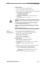
!
Warning
If the reference cam is not adjusted exactly, it is possible that a wrong zero
marker is evaluated after the reference cam has been left. As a result, the
control system will take a wrong machine zero.
Software limit switches, protection areas and work area limits will thus also be
active for the wrong positions. The difference corresponds to
"
one encoder
revolution.
Danger for man and machine exists.
The following machine data and interface signals are important:
MD 34040: REFP_VELO_SEARCH_MARKER (shutdown speed)
MD 34050: REFP_SEARCH_MARKER_REVERSE
(direction reversal to reference cam)
MD 34060: REFP_MAX_MARKER_DIST
(maximum path from cam to reference mark).
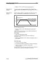
Properties of phase 2:
Feed override (the feed override switch) is not active.
100% is fixed, an abortion is carried out at 0%
Feed stop (channel-specific and axis-specific) is active. On feed stop the
axis stops and
– Alarm 20005 “Reference point approach canceled”
is output
The machine axis cannot be stopped or restarted using NC Stop/NC Start
If the machine axis travels a distance defined in MD 34060:
DB31, ... DBX12.7 (“Reference point approach delayed”) = 0
– MD 34060: REFP_MAX_MARKER_DIST (max. distance to the
reference mark)
and the zero mark is not detected, the machine axis stops and
Phase 2:
Synchronizing to the
encoder zero marker
10 NC Start-Up with HMI Advanced

