06.03
10.6 Digital and analog I/O devices
10-382
Siemens AG, 2003. All rights reserved
SINUMERIK 840Di Manual (HBI) – 06.03 Edition
10.6.4
Digital I/O bytes and system variables
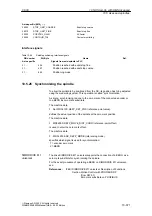
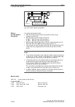
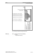
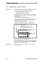
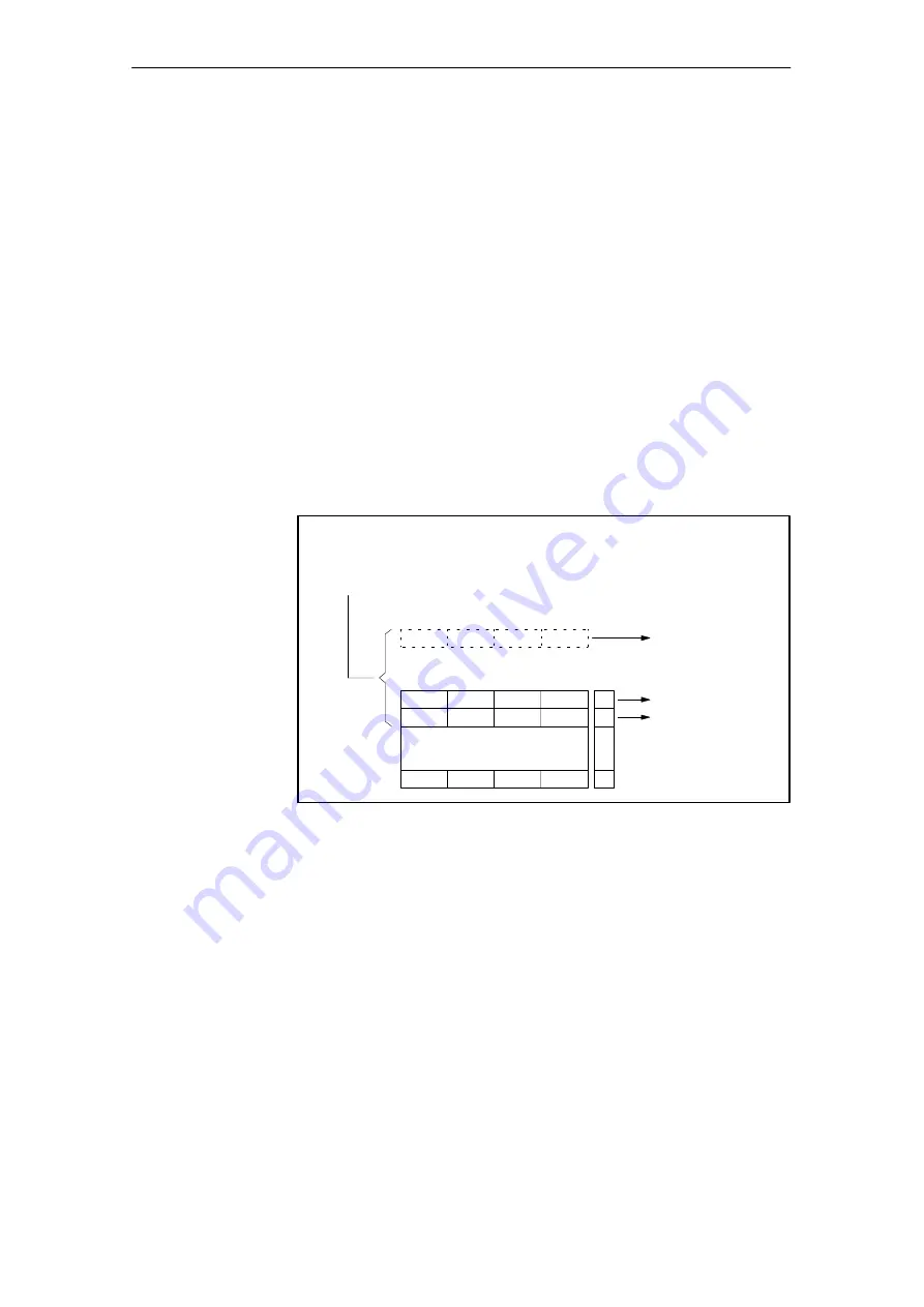
The following example uses the configuration of 3 digital input bytes to illustrate
the connection between digital input bytes and system variables.
The following prerequisites apply for the sample configuration:
–
MCI board extension module: 1 input byte.
–
PROFIBUS–DP signal modules: 2 input bytes
The MCI board extension module always uses one digital input byte. Digital
input bytes from external signal modules must therefore always be counted as
additional input bytes:
MD10350: FASTIO_DIG_NUM_INPUTS = 1 + m,
where m = number of input bytes from external signal modules
Since the 1st input byte is internally permanently assigned to the MCI board
extension module, only the input bytes of the external signal modules need to
be explicitly assigned to the system variables.
MD10366: HW_ASSIGN_DIG_FASTIN[0] –> 1. external input byte
MD10366: HW_ASSIGN_DIG_FASTIN[1] –> 2. external input byte
00
MD10350: FASTIO_DIG_NUM_INPUTS = 3 = 1 + m
where: 1
–>
1. Dig. input byte of the MCI board extension module
(alwazs permanently 1, see text)
m=2 –>
2nd and 3rd dig. input byte via PROFIBUS I/O modules
(number of input bytes used by external signal modules)
:
:
MD10366: HW_ASSIGN_DIG_FASTIN [n]
MCI board extension Module
I/O low
I/O high
05
00
I/O low
I/O high
05
System variable:
$A_IN[1] ... $A_IN[4]
$A_IN[9] ... $A_IN[16]
$A_IN[17] ... $A_IN[24]
0
1
n
Fig. 10-33 Sample configuration: 3 digital input bytes
If the optional MCI board extension module is not present, the assignment in the
machine data must still be carried out as specified, since the 1st input byte is
permanently assigned internally in this module. The system variables $A_IN[1]
bis $A_IN[4] then do not contaion any information.
The configuration of digital outputs is analogous to the example described
above for digital inputs.
Digital inputs
Digital outputs
10 NC Start-Up with HMI Advanced

