06.03
13.2 Measuring functions
13-419
Siemens AG, 2003. All rights reserved
SINUMERIK 840Di Manual (HBI) – 06.03 Edition
13.2
Measuring functions
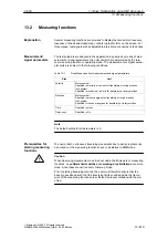
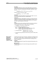
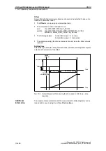
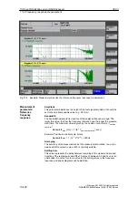
Several measuring functions are provided to display the time and/or frequency
response of drives and closed-loop controls in graphic form on the screen. For
this purpose, test signals with an adjustable interval are connected to the drives.
The test setpoints are adapted to the application in question by means of mea-
surement or signal parameters, the units of which are determined by the rele-
vant measuring function or operating mode. The measurement or signal param-
eter units are subject to the following conditions:
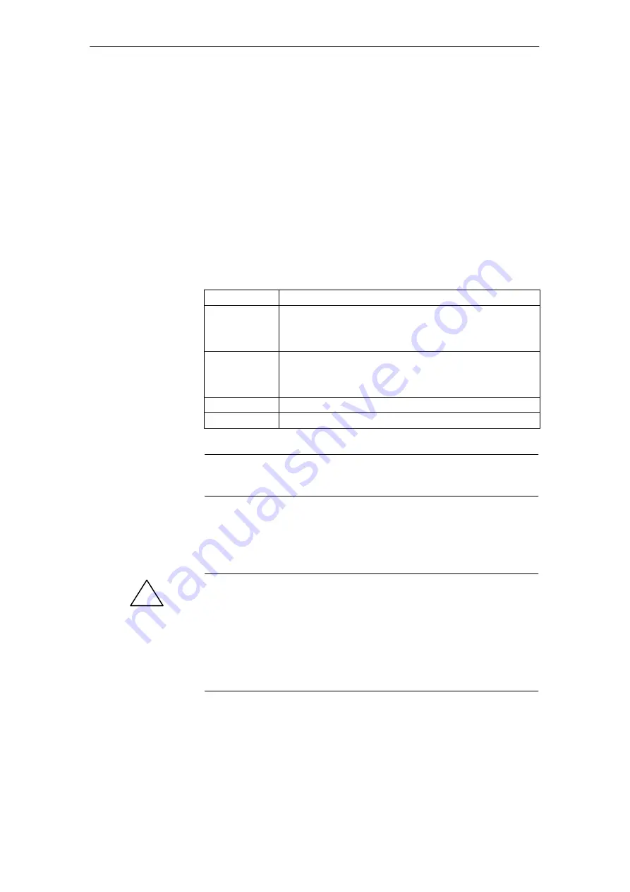
Table 13-1
Quantities and units of measurement and signal parameters
Size
Unit
Velocity
Metric system:
Specified in mm/min or rev/min for translatory or rotary motions
Inch system:
Specified in inch/min or rev/min for translatory or rotary motions
Distance
Metric system:
Specified in mm or degrees for translatory or rotary motions
Inch system:
Specified in inches or degrees for translatory or rotary motions
Time
Specified in msec
Frequency
Specified in Hz
Note
The default setting for all parameters is 0.
To ensure that no erroneous traversing movements due to parts programs can
be carried out, the measuring functions have to be started in JOG mode.
!
Caution
When traversing movements are carried out within the framework of measuring
functions, no software limit switches and working area limitations are moni-
tored, since these are carried out in follow-up mode.
Prior to starting traversing motions, the user must therefore ensure that the
axes are positioned such that the traversing limits specified within the frame-
work of the measuring functions are sufficient to prevent collision with the ma-
chine.
Explanation
Measurement/
signal parameters
Prerequisites for
starting measuring
functions
13 Drive Optimization using HMI Advanced

