06.03
13.4
Frequency response measurement
13-423
Siemens AG, 2003. All rights reserved
SINUMERIK 840Di Manual (HBI) – 06.03 Edition
13.4
Frequency response measurement
You can measure both digital and analog drives. However, the bandwidth avail-
able for measuring is limited by the position controller or PROFIBUS cycles.
Note
You will find detailed information about frequency measurement and optimiza-
tion of the torque/current and speed control loop of the SIMODRIVE 611 univer-
sal/E, POSMO CD/CA and SI drives in the online help of the start-up tool Simo-
Com U:
Menu command: Help > Help topics > Index
–
Measuring function
–
Optimization of speed control loop.
13.4.1
Measurement of the torque control loop
A measurement of the torque control loop with HMI Advanced is not possible
within the framework of SINUMERIK 840Di.
13.4.2
Speed control loop measurement
Note
You will find information about optimization of the torque/current and speed
control loop of the SIMODRIVE 611 universal/E, POSMO CD/CA and SI drives
in the online help of the start-up tool SimoCom U, Index: Optimization of speed
control loop.
This measurement function basically analyses the response to the motor mea-
suring system. Depending on which basic measurement setting has been se-
lected, various measurement parameters lists as described below are made
available.
The traversing range monitoring function is set and the enabling logic (external/
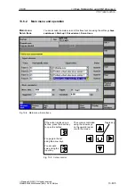
internal) selected in the speed control loop measurement main screen.
1. Set the traversing range monitoring function and enabling logic in the main
menu.
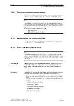
Four different types of measurement are available for testing the speed con-
trol loop:
–
Reference frequency response
–
Setpoint step change
–
Interference frequency response
–
Disturbance step change
–
Speed controller system
Functionality
Procedure
13 Drive Optimization using HMI Advanced

