06.03
13.4 Frequency response measurement
13-424
Siemens AG, 2003. All rights reserved
SINUMERIK 840Di Manual (HBI) – 06.03 Edition
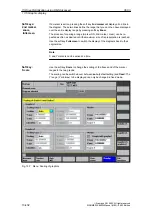
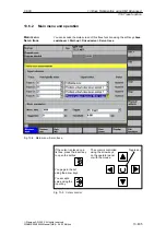
2. Set the required parameters in the measurement parameter screen.
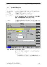
3. Display of the measurement result on the screen with the soft key Display.
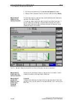
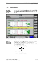
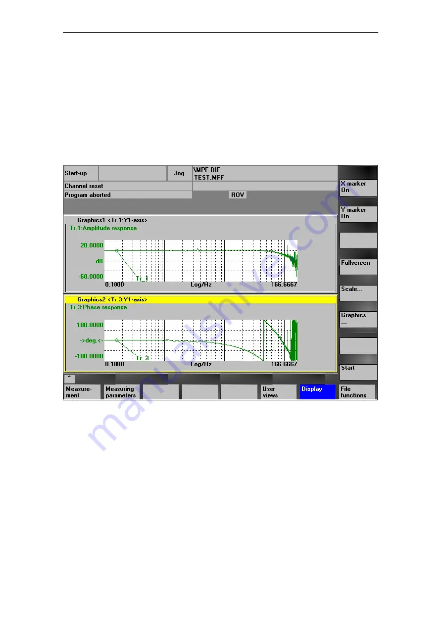
The reference frequency response measurement determines the transmission
response of the speed controller.
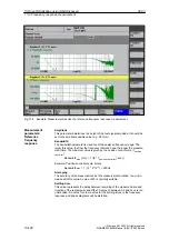
The response range should be as wide as possible and without resonance. It
may be necessary to install stop or low-pass filters. Particular care must be
taken to prevent resonance within the speed controller limit frequency range
(stability limit approx. 200–500Hz).
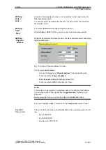
Fig. 13-2 Example: Measurement results of a reference frequency response measurement
Alternatively, the interference frequency response can be recorded in order to
assess how well the control suppresses interference.
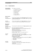
Amplitude
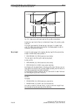
This parameter determines the height of the test signal amplitude. This should
give rise to only a very low speed of a few (approximately 1 to 2) revs/min at the
motor end.
Measurement:
Reference fre-
quency response
Measurement:
Interference fre-
quency response
Measurement
parameters:
Reference and
interference
frequency
response
13 Drive Optimization using HMI Advanced

