06.03
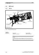
2.2 MCI board
2-48
Siemens AG, 2003. All rights reserved
SINUMERIK 840Di Manual (HBI) – 06.03 Edition
2.2.2
Interface description
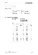
Interfaces of the MCI board module
Table 2-1
Interface overview: MCI board
Interface
Designation
Type
PROFIBUS DP
X101
Socket connector
MPI
X111
Socket connector
MCI board extension
X2
Plug connector
Backup battery
X3
Plug connector
PCI bus
X11
Direct connector
Interface description of the battery connection (X3):
S
Connection: 2-pin plug connector
S
Pin assignment.
Table 2-2
Pin assignment: Battery connection (X3)
Pin
Designation
Type
1)
Function
1
BATT–
VI
Minus pole of the battery
2
BATT+
VI
Plus pole of the battery
1.
VI
Voltage Input
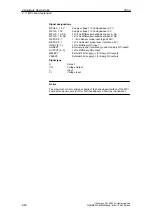
Interface description PROFIBUS DP interface (X101):
S
Connection: 9-pin SUB-D socket connector
S
Pin assignment.
Table 2-3
Pin assignment: PROFIBUS DP interface (X101)
Pin
Designation
Type
1)
Function
1
Not assigned
–
–
2
Not assigned
–
–
3
RS-DP
B
RS-485 differential signals
4
RTS
O
Request to Send
5
GNDext
VO
External ground
2)
6
P5ext
VO
Ext. 5V power supply
2)
7
Not assigned
–
–
8
XRS DP
B
RS-485 differential signals
9
Not assigned
–
–
1st VO
Voltage Output
O
Output
B
Bidirectional
2) Pins 5 and 6 are only allowed to be used to supply power to the bus terminators
S
Connection cable
see Subsection 3.3.1, Page 3-131.
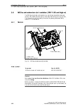
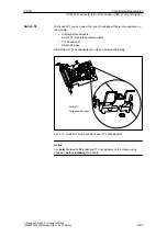
Interface overview
Battery connection
(X3)
PROFIBUS DP
interface
(X101)
2 Hardware Descriptions

