06.03
16.2 Expanded message frame configuration (SW 2.2 and higher)
16-509
Siemens AG, 2003. All rights reserved
SINUMERIK 840Di Manual (HBI) – 06.03 Edition
!
Warning
For reasons relating to the system, the consistency check – which is performed
during SINUMERIK 840Di boot and based on acyclic communication with the
drive – runs parallel in time with the already active cyclic communication be-
tween NC and drive.
As setpoint and actual values are already being exchanged between the NC
position control and drive as part of the cyclic communication, uncontrolled
system states can occur on the drive side due to faulty process data configura-
tions which cannot be detected yet at this point in time.
The same applies if acyclic communication is not supported by a drive, or if
acyclic communication was deactivated for a drive via the axis-specific NC ma-
chine data:
S
MD 13070: DRIVE_FUNCTION_MASK[n] (used DP functions)
and therefore it is not possible for the NC to perform a consistency check.
Therefore, the responsibility lies with the start-up engineer to implement suit-
able measures (e.g. connecting terminals 64/65A/65B/ 663) to avoid uncon-
trolled traversing of the drives during start-up, caused by inconsistencies in the
above mentioned data.
An error can present a risk of danger to person or machine.
16.2.5
Data descriptions (MD, system variable)
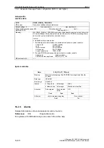
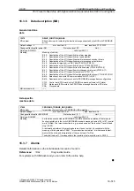
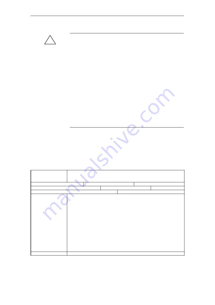
13070
DRIVE_FUNCTION_MASK
MD number
Bit-coded screen for selecting the functional scope expected by the NCK with PROFIBUS
drives
Default settings: 0
min. input limit: 0
max. input limit: FFFF FFFF
Changes effective after power ON
Protection level: 2/7
Unit: –
Data type: DWORD
valid from SW: 2.1
Meaning:
Meaning of set bits:
Bit 0: Deactivation of the 611U-specific drive alarm mapping
Bit 1: Deactivation of the 611U-specific drive type detection
Bit 2: Deactivation of the 611U-specific parameter accesses encoder drivers
Bit 3: Deactivation of the 611U-specific parameter accesses output drivers
Bit 4: Activation third-party drive: DSC bits (CTW1.12/STW1.12)
Bit 5: Deactivation of the 611U-specific drive parks (CTW2.7/STW2.7)
Bit 6: Deactivation of the 611U-specific travel to fixed stop (CTW2.8/STW2.8)
Bit 7: Deactivation of the 611U-specific motor changeover internal (STW2.9–11)
Bit 8: Deactivation of the 611U-specific ramp block (CTW1.13)
Bit 9: Deactivation of the 611U-specific function generator functions (CTW1.8/STW1.13)
Bit 14: Selection of non-cyclic DP communication: 0=DPT; 1=DPV1
Bit 15: Deactivation of consistency check for PROFIBUS message frame configuration
CTW:
Control word (PDA word in the PROFIDrive message frame to DP slave)
STW:
Status word (PDA word in the PROFIDrive message frame from DP slave)
PDA:
Process data
MD irrelevant with ......
–––
General machine
data
16 840Di Specific Data and Functions

