06.03
2.4 MCI board extension slot variation (SW 11.00 and higher)
2-65
Siemens AG, 2003. All rights reserved
SINUMERIK 840Di Manual (HBI) – 06.03 Edition
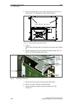
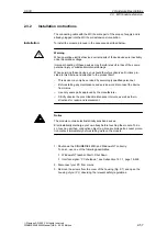
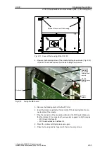
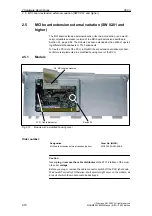
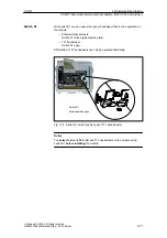
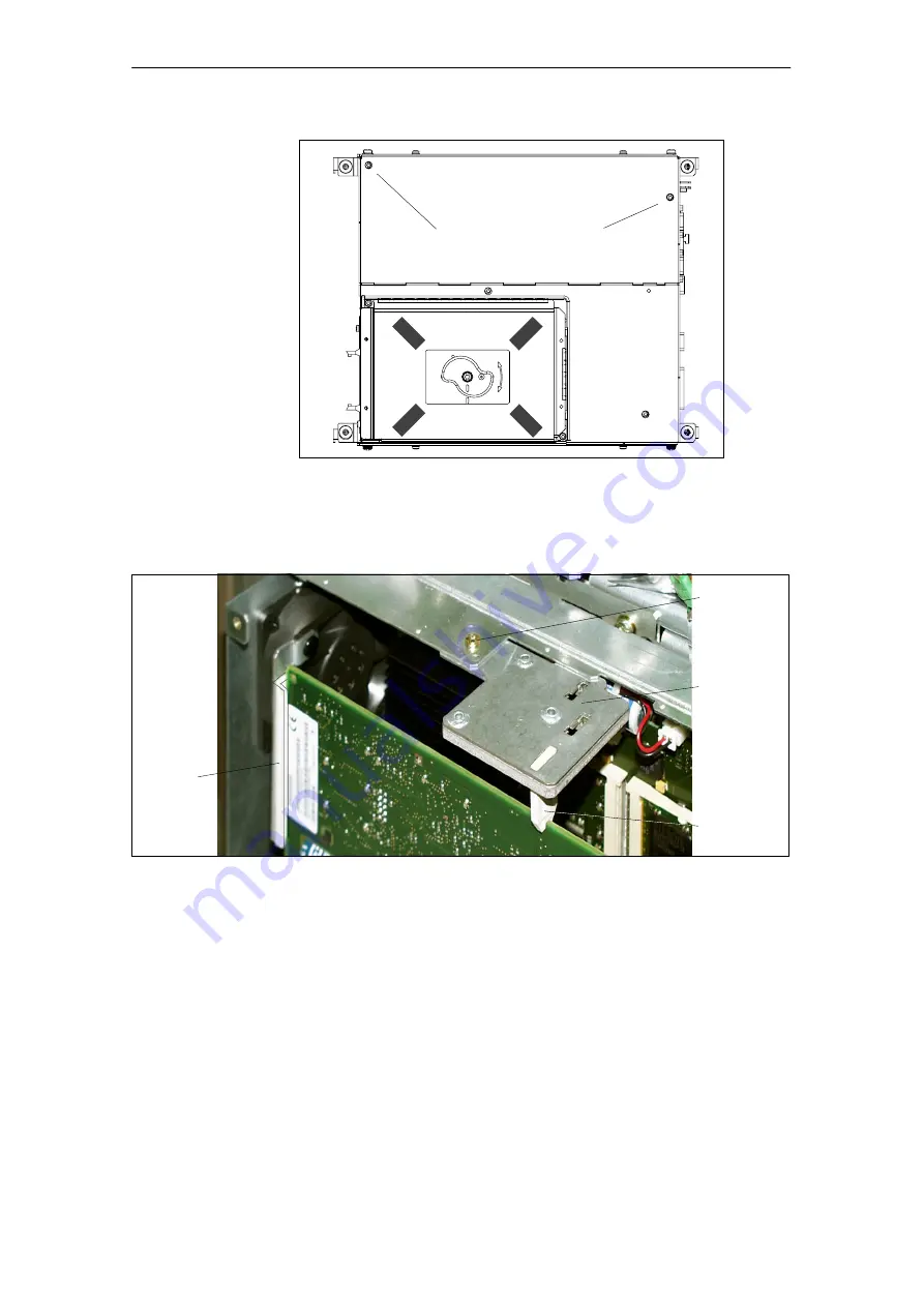
Screws of the cover of the housing
Fig. 2-11 Cover of the housing of the PCU 50
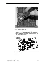
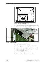
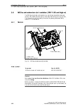
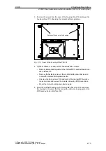
4. Remove the fastening screw of the module holding-down device (Fig. 2-12)
of the MCI board and remove the module holding-down device.
Module
holding-down
device
Fastening
screws for
the module
holding-down
device
Plastic
holder
Guide rail
Fig. 2-12
Fixing the MCI board
5. Remove the blanking plate of the free PCI slot.
6. Insert the module carefully but firmly into the PCI slot and tighten the con-
nector plate of the module.
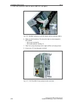
7. Plug the connector of the connecting cable into the MCI board. Make sure
that the latches of the connectors have securely engaged on both modules.
–
MCI board: Interface X2
–
MCI board extension: Interface X4
8. Mount the module holding-down device again.
9. Close the housing and fix it again with the two housing screws.
2 Hardware Descriptions

