06.03
2.6 Cable distributor
2-77
Siemens AG, 2003. All rights reserved
SINUMERIK 840Di Manual (HBI) – 06.03 Edition
the “teeth” of the lower terminal clamp and then fasten the upper part of the
housing.
This will reliably press the cable shields between the contact areas of the
contact springs and contact them safely. The shield potential is reliably routed to
the housing of the PCU using the contact springs of the cable distributor on the
front panel of the PCU.
open
closed
X1
X2
X4
X5 X6
X7
X8
X9
X10
X3
X11
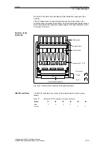
Cable guides
Terminal clamp
Contact areas
Connectors X1...X10
S3
S4
S5
S1
S2
Sub-D socket connector
S6
S1 to S6:
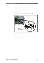
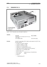
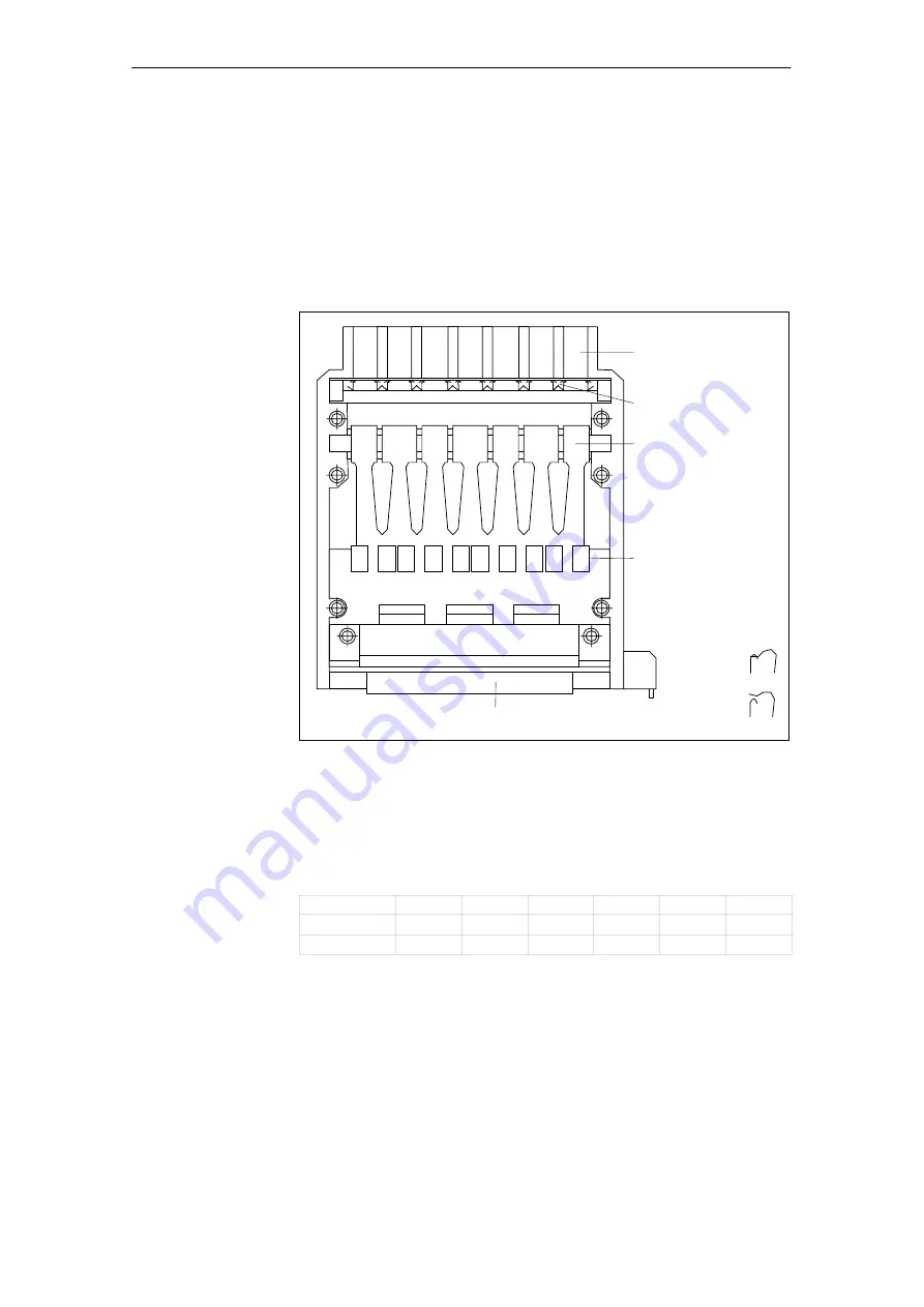
Fig. 2-20 Position of the interfaces of the cable distributor
The DIP-FIX switches in the interior of the cable distributor must be set as
follows:
Table 2-11
Setting the DIP-FIX switches in the cable distributor
Switch
S1
S2
S3
S4
S5
S6
open
X
X
X
X
closed
X
X
Position of the
interfaces
DIP-FIX switches
2 Hardware Descriptions

